
Chip-Tools
Bench or BSL (boot mode): choosing the right connection for a Bosch EDC17/ME17/MED17 ECU
Strumenti
Interface Classic
Flashing / Programming
Medium
⏱ 20-40 min
10 steps
The wiring-diagram appendix of the ECU Programming Tool manual lists, ECU by ECU, how to hook it up off the vehicle. For every ECU the manual gives the Bench connection and, where needed, the BSL (boot mode) connection: this guide explains how to read that appendix and pick the right route before you touch a wire.
Required licences
- —
Hardware / cables
⚠ WarningNever use the diagram for a "similar" ECU: the manual separates very close designations (EDC17C10 Variant 1 and Variant 2, EDC17C84 Old and new, MED17.1.1 with TC1796 and with TC1797) and the connections do not match. Some ECUs, such as the EDC17C45 TC1767 Renault/Nissan, are listed as BSL only: on those there is no bench route at all.
Procedure
- Read the ECU label and note the exact Bosch designation (for example EDC17C64, ME17.5.24, MED17.5.25) and the vehicle make.
- Find the heading in the manual appendix that matches the designation exactly: each entry also gives the Tricore microcontroller (TC1724, TC1762, TC1766, TC1767, TC1782, TC1792, TC1793, TC1796, TC1797) and the list of makes covered.
- Check that the microcontroller named in the heading is the one actually fitted on the board: under the same commercial designation the manual lists different variants (for example MED17.1.1 TC1796 for Audi/Volkswagen and MED17.1.1 TC1797 for Audi, Bentley, Lamborghini, Porsche), each with its own diagram.
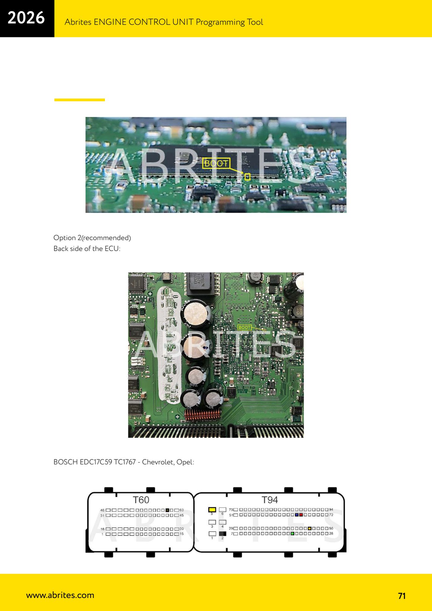
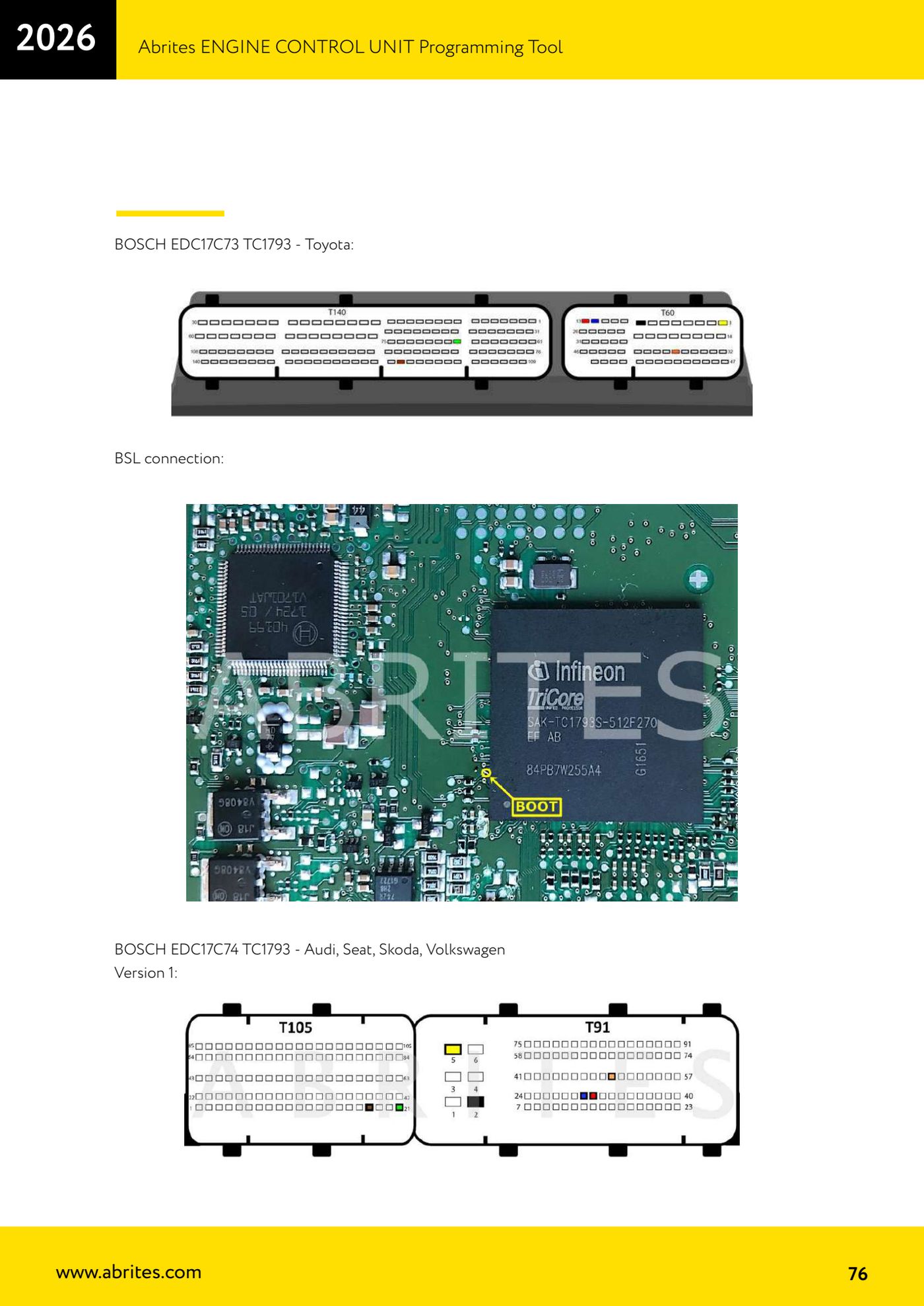
- Look at which diagrams appear under that entry: if there is only the base diagram, it is a Bench job; if a "BSL connection" heading appears below it, the ECU has to be put into boot mode using the extra connection shown.
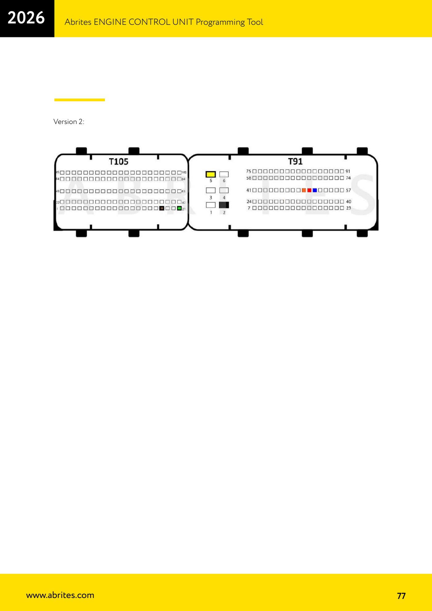
- If the entry has several drawings marked "Option 1"/"Option 2" or "Version 1"/"Version 2"/"Version 3", pick the one matching the PCB in front of you; where the manual flags an option as "recommended", start with that one.
- Check whether the diagram refers to the component side or the solder side: the manual states it where it matters (for example "Front side of the ECU" and "Back side of the ECU"), and getting the side wrong means soldering to the wrong pads.
- Only open the ECU if the chosen diagram calls for points on the board; if the diagram works on the connector instead, build your breakout on the ECU connector following the pin numbering in the drawing.
- Build the loom following the wire colours shown in the drawings (for example CAN HIGH in red and CAN LOW in blue) and double-check every wire before applying power.
- Connect the AVDI, power up the ECU and start the read from the software: if the ECU does not answer on Bench, re-check the diagram before moving to BSL, because boot mode needs the additional connection shown in the "BSL connection" section of the same page.
- Before any write, save and keep the original file you read out: it is the only way back if programming is interrupted.
Reference screenshots
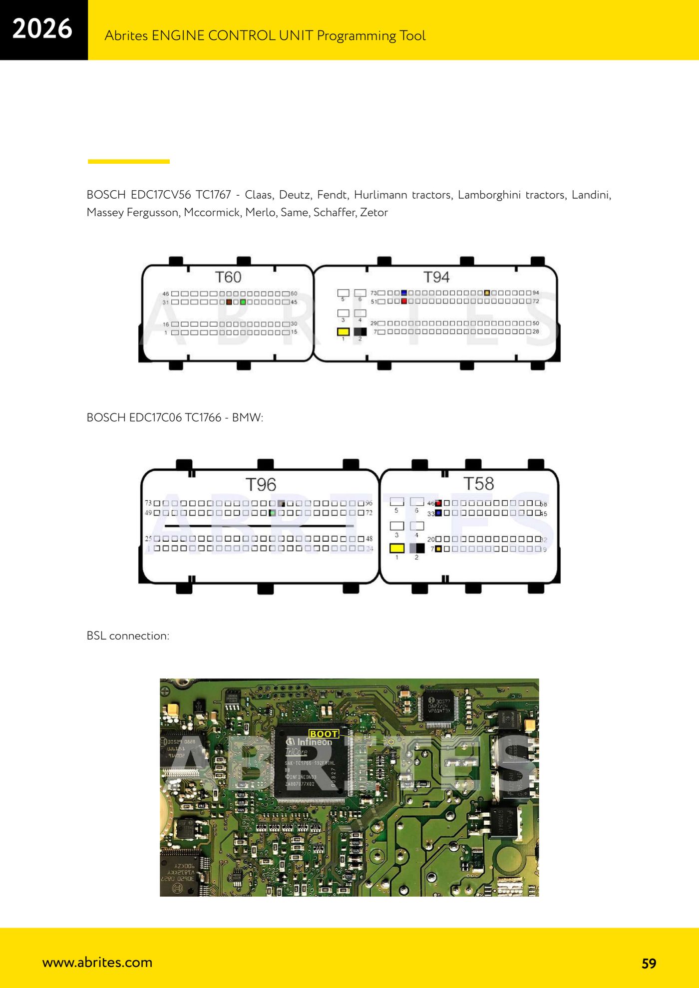
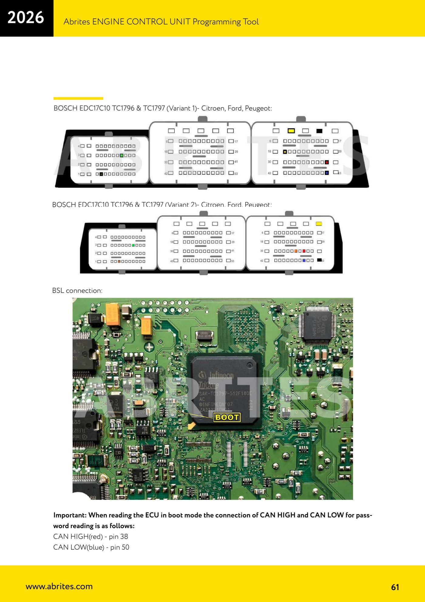
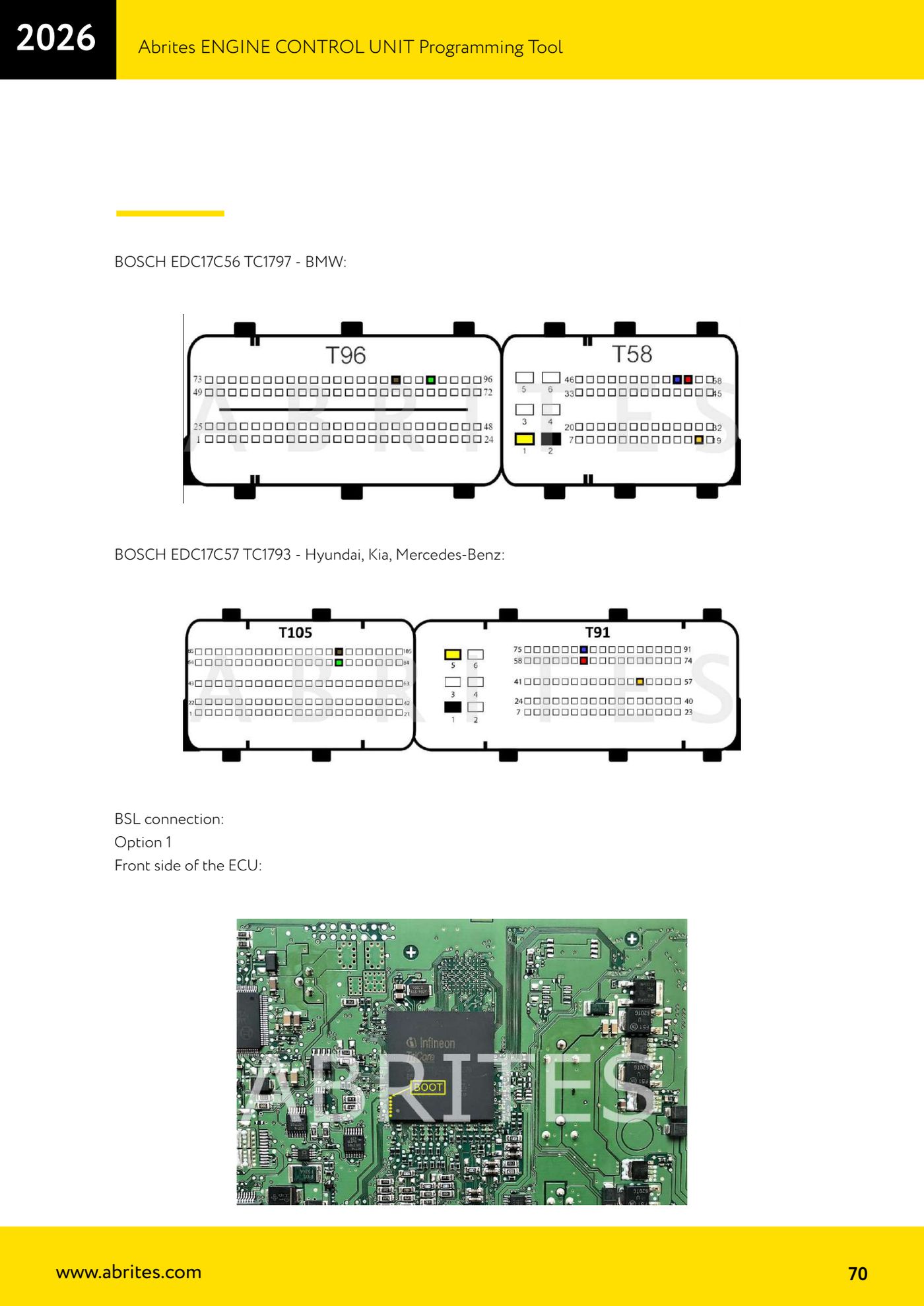
Source: Manuale ECU Programming Tool, parte 2 di 3, appendice schemi di collegamento (p.54-106) · ⏱ estimated time 20-40 min
← All Abrites guides Hardware catalogue
More guides Strumenti
- ABPROG ZN030: what's in the set, hooking it up to the AVDI and starting the Classic software
- Reading and writing SPI, I2C and Microwire EEPROMs with ABPROG and the ZN031/ZN035 adapter
- Erasing and reprogramming M35080VP / M35080V6 incremental EEPROMs with ABPROG
- Wiring an SPI EEPROM straight to the ABPROG DB25 without the ZN031 adapter
- Mercedes-Benz IR keys: reading the SSID, erasing and programming the NEC with ZN032 / ZN033
- Renewing used keys (HITAG/PCF) with the ZN046 adapter and ABPROG
- Solder points on key PCBs for the ZN046 and list of keys supported for renewal
- Reading the EWS3 dump on BMW E46/E39/E53 and others with the ZN055 adapter
- Reading the EEPROM on BMW F-Series FEM/BDC without desoldering, using the ZN057 extension
- Reading and writing NEC V850ES MCUs with the ZN078 adapter and ABPROG
- ABPROG DB25 pinout: building your own ZN046, ZN058, ZN078 and ZN086 adapters
- Reading the immobiliser from a Renault X95 BCM (and Audi BCM) with ABPROG and direct wiring