
Chip-Tools
Bosch EDC17CPxx PIN OUT and BSL diagrams: finding the right diagram for your ECU
Strumenti
Interface Classic
Hardware / Connections
Advanced
⏱ varies
8 steps
The diagrams chapter of the manual carries, for every Bosch EDC17CPxx variant, the pin diagram for bench connection and the "BSL connection" diagram for boot mode. This guide explains how to find the right diagram starting from the ECU designation and the Tricore processor.
⚠ WarningEvery diagram applies to one specific EDC17CPxx designation / processor combination: using the wrong diagram means putting voltage on the wrong pins. Always connect GND first and check the wiring before powering the Distribution Box.
Procedure
- Read the full designation off the ECU label (for example EDC17CP44) and, if you open it, the Tricore processor designation (TC1766, TC1792, TC1793, TC1796, TC1797).
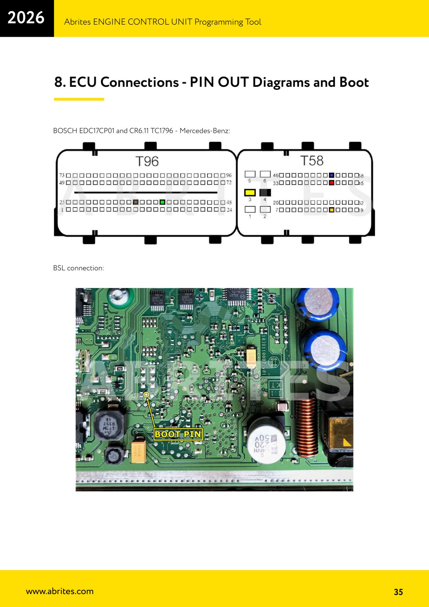
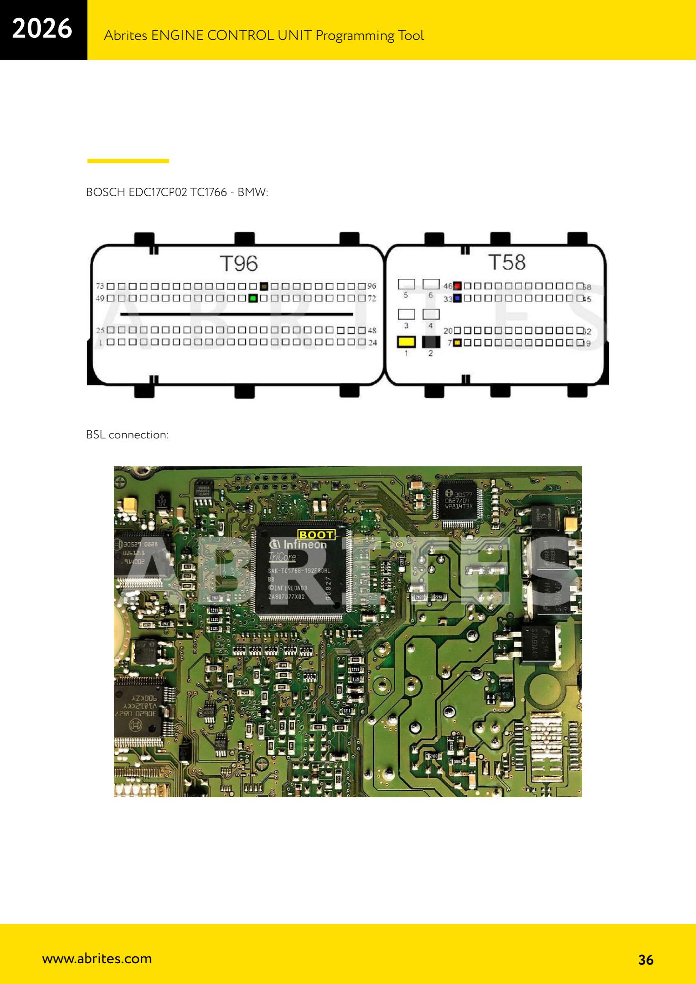
- Look up the diagram with the same designation in the manual: some variants are listed with the vehicle manufacturer, for example EDC17CP01 and CR6.11 TC1796 - Mercedes-Benz; EDC17CP02 TC1766 - BMW; EDC17CP04 TC1796 - Audi, Volkswagen; EDC17CP07 TC1766 - Toyota; EDC17CP09 TC1766 and TC1796 - BMW; EDC17CP10 TC1796 - Mercedes-Benz.
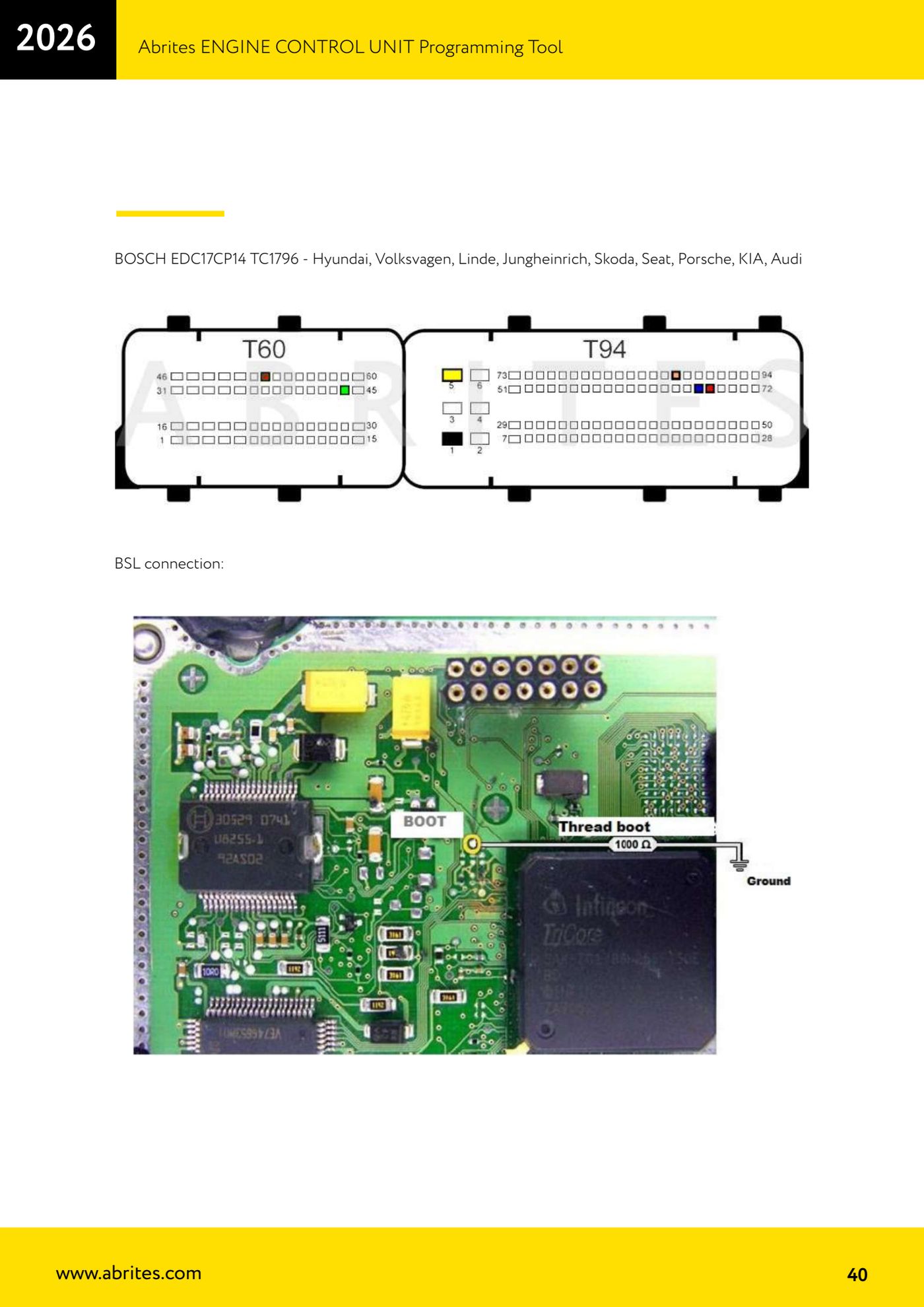
- Other common variants: EDC17CP11 TC1796 - Jaguar, Land Rover, Renault; EDC17CP14 TC1796 - Hyundai, Volkswagen, Linde, Jungheinrich, Skoda, Seat, Porsche, KIA, Audi; EDC17CP16 TC1792 - Honda; EDC17CP18 TC1796 - GMC, Chevrolet; EDC17CP19 TC1766 - Renault, Saab; EDC17CP20 TC1796 - Audi, Volkswagen, Hako; EDC17CP22 TC1796 - Volvo; EDC17CP24 TC1796 - Audi, Volkswagen.
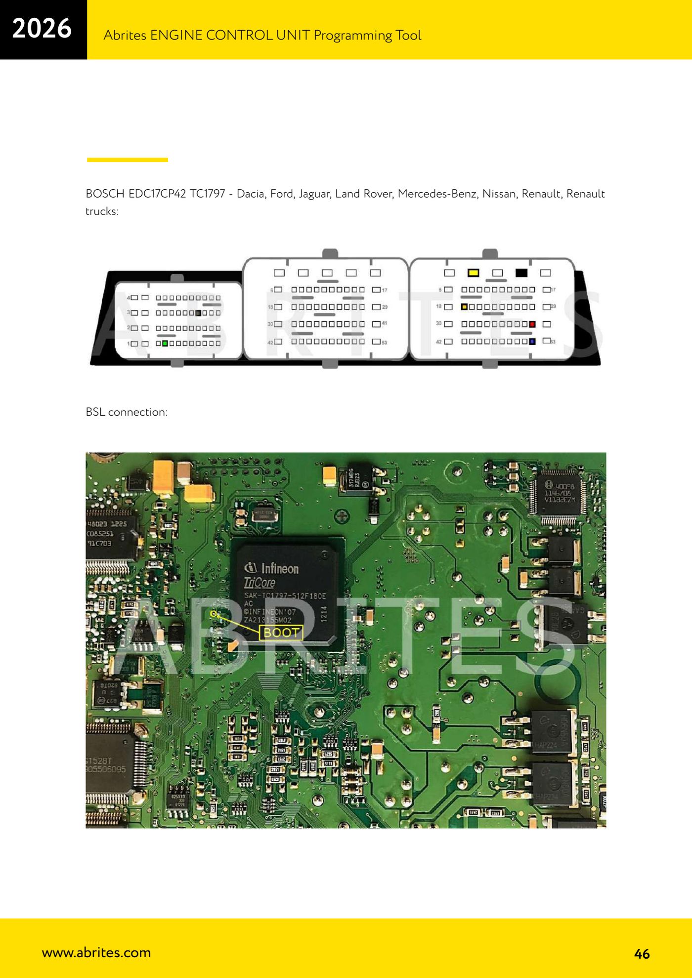
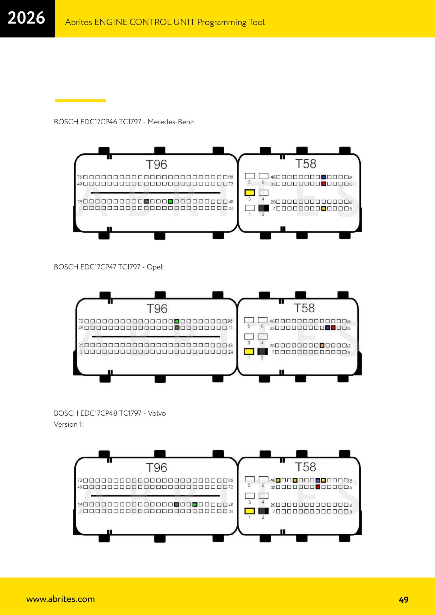
- And further: EDC17CP37 TC1766 - Toyota; EDC17CP42 TC1797 - Dacia, Ford, Jaguar, Land Rover, Mercedes-Benz, Nissan, Renault, Renault trucks; EDC17CP44 TC1797 - Volkswagen, Audi, Porsche; EDC17CP45 TC1796 and TC1797 - BMW; EDC17CP46 TC1797 - Mercedes-Benz; EDC17CP47 TC1797 - Opel; EDC17CP48 TC1797 - Volvo (careful: there is a Version 1 and a Version 2, check which one matches your board).
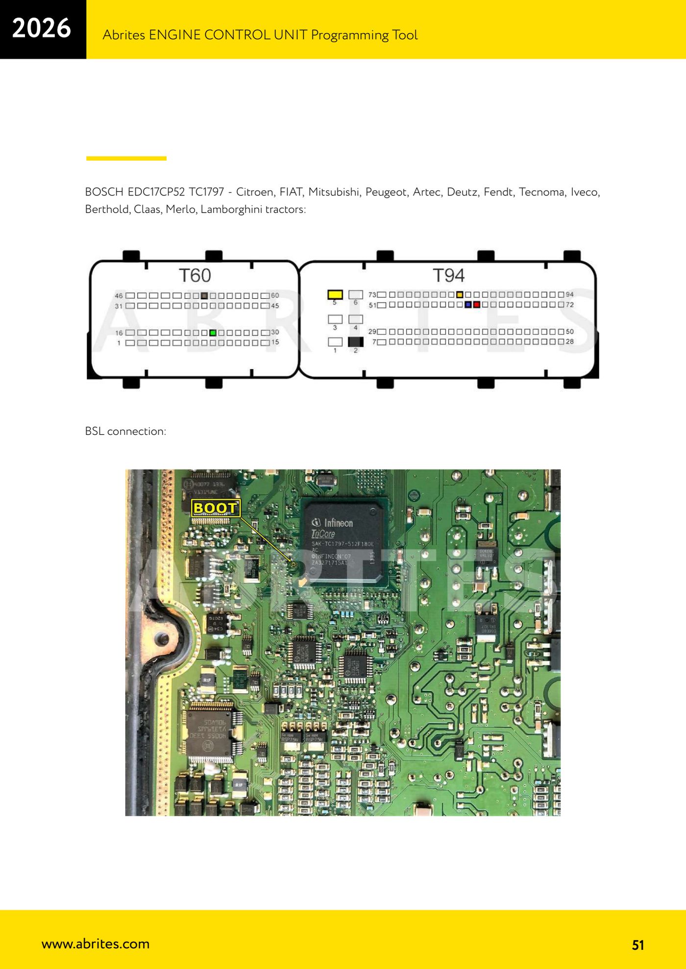
- Finally: EDC17CP49 TC1796 and TC1797 - BMW, Lindner; EDC17CP50 TC1797 - Honda; EDC17CP52 TC1797 - Citroen, FIAT, Mitsubishi, Peugeot, Artec, Deutz, Fendt, Tecnoma, Iveco, Berthold, Claas, Merlo, Lamborghini tractors; EDC17CP54 TC1793 - Audi, Volkswagen; EDC17CP55 TC1793 - Jaguar, Land Rover, Mahindra.
- If the diagram shows a "BSL connection" section, that is the connection variant to use in boot mode, with the boot pin to be soldered and the resistors stated; the rest of the diagram is for the bench connection.
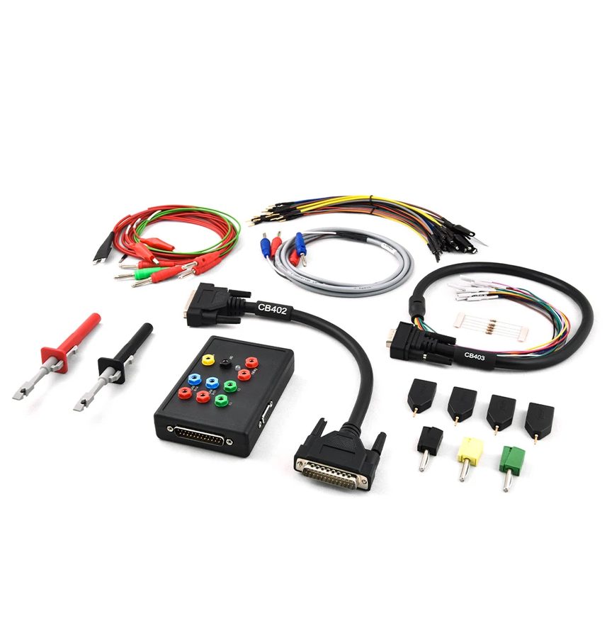
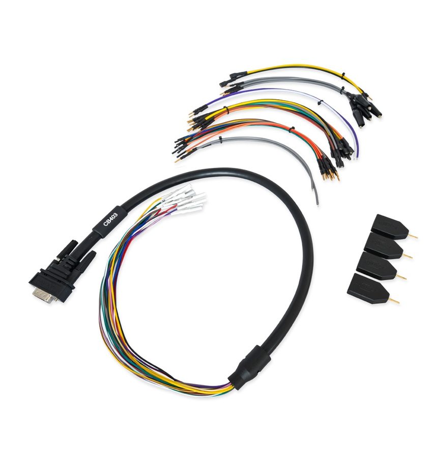
- Translate the diagram into the wires of your cable: with the CB401 use the legend B+, IGN, GND, CAN HI (CAN6), CAN LOW (CAN14), T1, T2, Boot; with the CB403 use the HD15 pinout (IGN, B+, K-LINE 1, BOOT 2, BOOT 1, T2, T1, CAN H, T3, T4, GND, GND, B+ PERMANENT, CAN L, K-LINE 7).
- Wire it starting from GND, then connect the DB15 to the ZN151 and finally power the box with 12V; only at that point start the read from "Bench" or "BSL" in the software.
Reference screenshots
Source: Manuale ECU Programming Tool, parte 1 di 3, cap. 8 (p.35-53) · ⏱ estimated time varies
← All Abrites guides Hardware catalogue
More guides Strumenti
- ABPROG ZN030: what's in the set, hooking it up to the AVDI and starting the Classic software
- Reading and writing SPI, I2C and Microwire EEPROMs with ABPROG and the ZN031/ZN035 adapter
- Erasing and reprogramming M35080VP / M35080V6 incremental EEPROMs with ABPROG
- Wiring an SPI EEPROM straight to the ABPROG DB25 without the ZN031 adapter
- Mercedes-Benz IR keys: reading the SSID, erasing and programming the NEC with ZN032 / ZN033
- Renewing used keys (HITAG/PCF) with the ZN046 adapter and ABPROG
- Solder points on key PCBs for the ZN046 and list of keys supported for renewal
- Reading the EWS3 dump on BMW E46/E39/E53 and others with the ZN055 adapter
- Reading the EEPROM on BMW F-Series FEM/BDC without desoldering, using the ZN057 extension
- Reading and writing NEC V850ES MCUs with the ZN078 adapter and ABPROG
- ABPROG DB25 pinout: building your own ZN046, ZN058, ZN078 and ZN086 adapters
- Reading the immobiliser from a Renault X95 BCM (and Audi BCM) with ABPROG and direct wiring