
Chip-Tools
Mercedes TCU bench pinouts: VGSNAG3 9G-Tronic, VGSNAG2-FDCT and Getrag 7DCT300
Strumenti
Interface Classic
Hardware / Connections
Medium
⏱ 30-60 min
6 steps
Bench connection diagrams for the Mercedes transmission control units: VGSNAG3 9G-Tronic, VGSNAG2-FDCT and Getrag 7DCT300. With the connection made correctly you can read and write the TCU's Data Flash, Program Flash and maps.
Required licences
- —
Hardware / cables
 AVDI
AVDI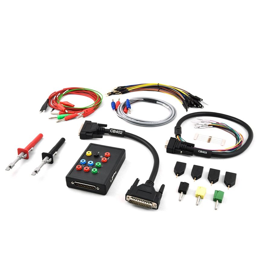 ZN151 DS Box
- CB401
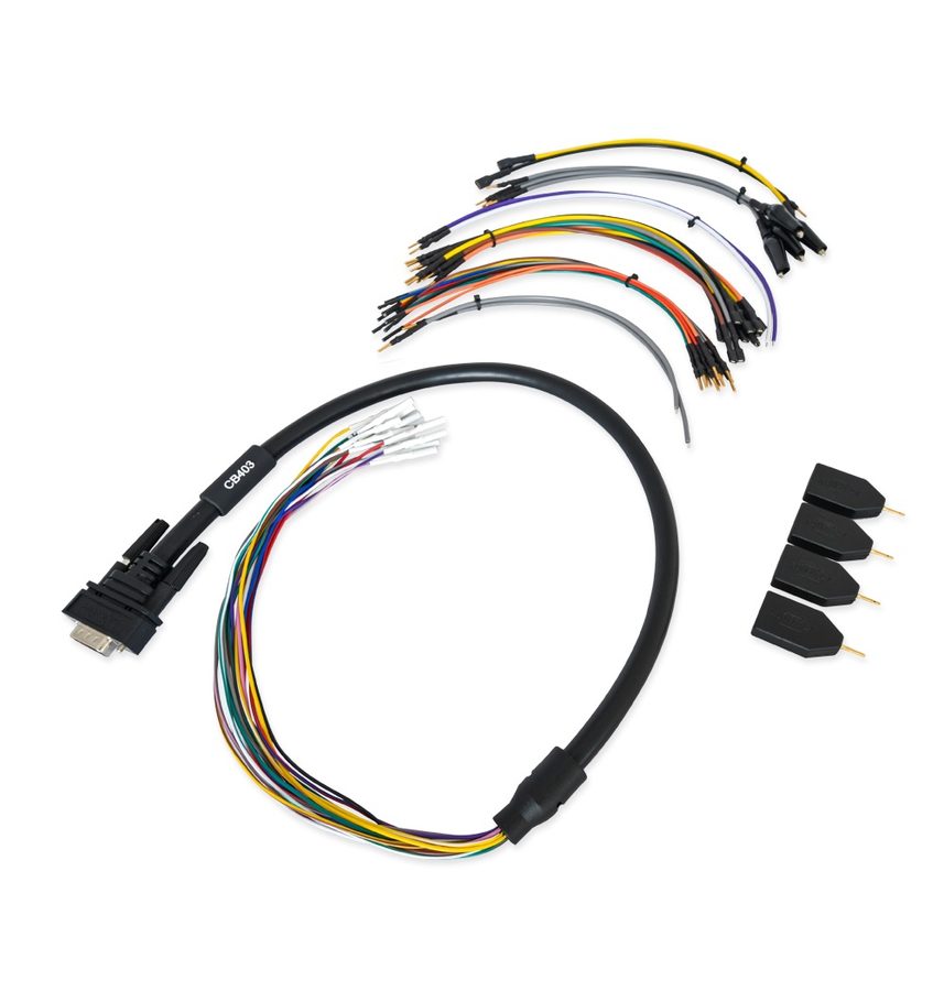 CB403
CB403- alimentatore 12V
⚠ WarningThe VGSNAG2-FDCT connector has no ground pin: the black GND lead goes onto any point of the TCU's metal housing. Do not go looking for a ground on the connector and do not invent a pin.
Procedure
- Prepare the set: these TCU units need the ZN151 DS Box and a CB401 or CB403 cable connected to the AVDI.
- For the VGSNAG3 9G-Tronic follow the dedicated connection diagram in the manual, landing power, ground and CAN lines on the pins shown.
- For the VGSNAG2-FDCT connect power and CAN as per the diagram, then take the black ground lead straight onto the unit's metal housing, because the connector has no GND pin.
- For the Getrag 7DCT300 use connector B with this pinout: PIN 1 = 12V+, PIN 6 = GND, PIN 19 = 12V+, PIN 33 = CAN H, PIN 34 = CAN L. You need the ZN151 DS Box and CB401/CB403.
- Check the wiring with the bench unpowered, then apply voltage and start the ECU Programming Tool.
- With the connection right you can read and write Data Flash, Program Flash and the TCU maps: always start from a full read saved to file.
Reference screenshots
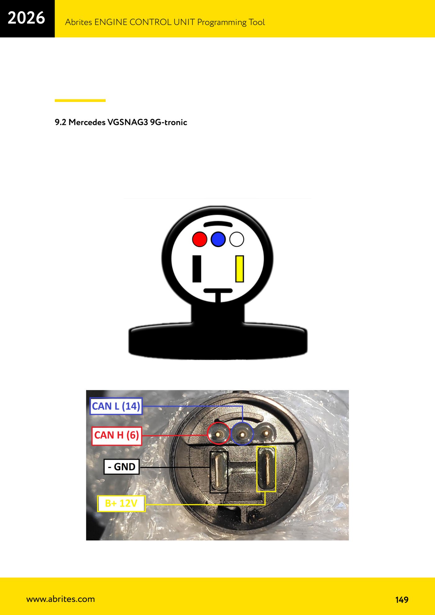
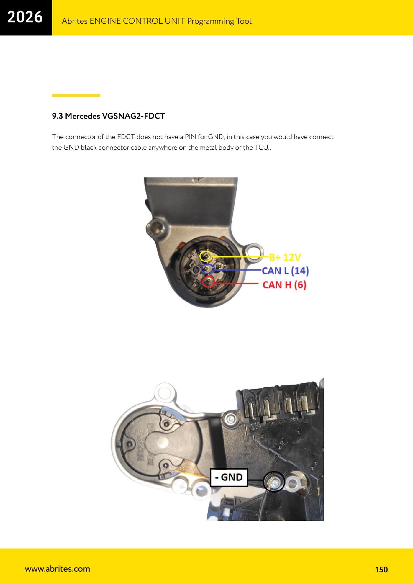
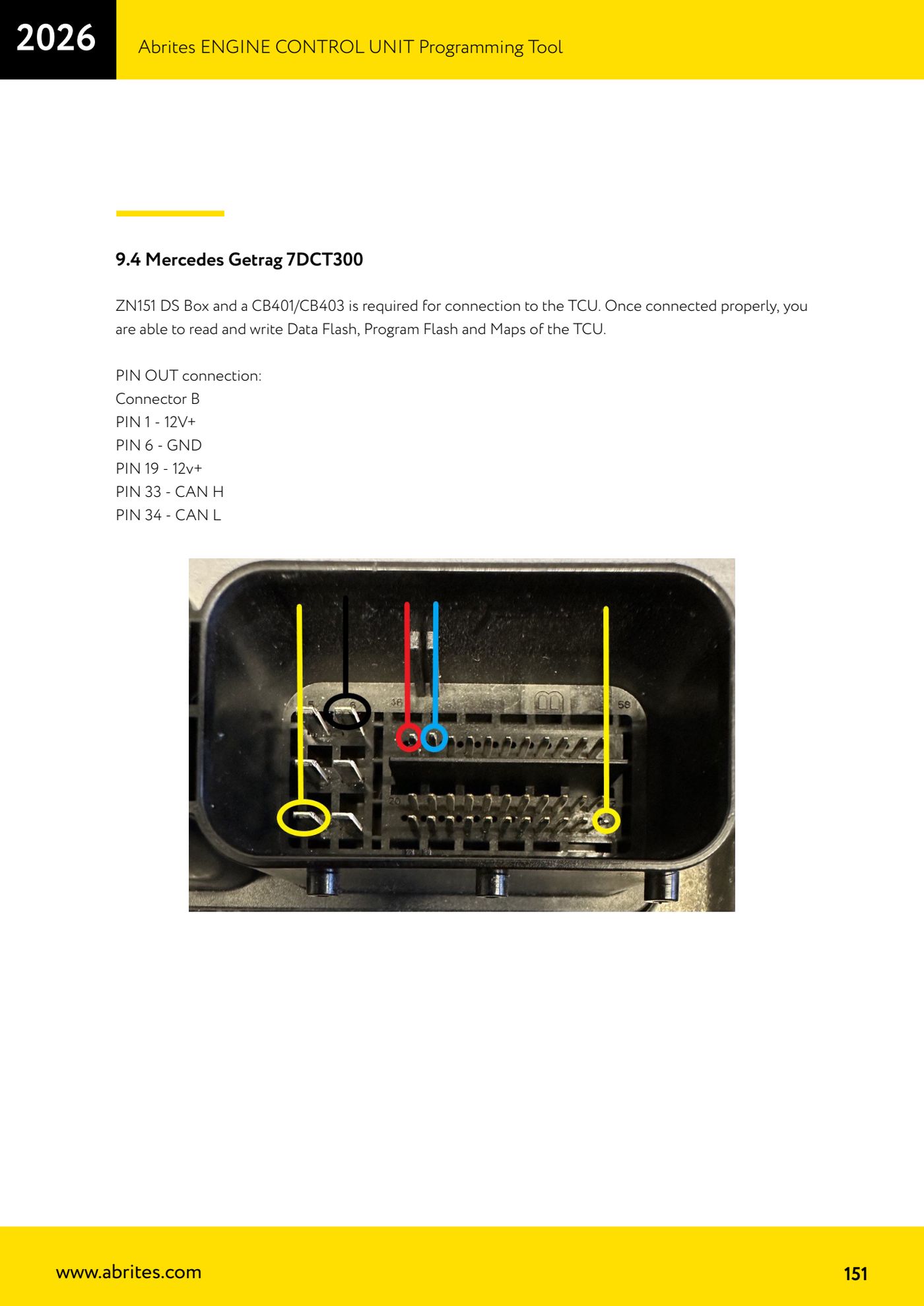
Source: Manuale ECU Programming Tool, parte 3 di 3, cap. 9.2-9.4 - Mercedes VGSNAG3 / VGSNAG2-FDCT / Getrag 7DCT300 (p.149-151) · ⏱ estimated time 30-60 min
← All Abrites guides Hardware catalogue
More guides Strumenti
- ABPROG ZN030: what's in the set, hooking it up to the AVDI and starting the Classic software
- Reading and writing SPI, I2C and Microwire EEPROMs with ABPROG and the ZN031/ZN035 adapter
- Erasing and reprogramming M35080VP / M35080V6 incremental EEPROMs with ABPROG
- Wiring an SPI EEPROM straight to the ABPROG DB25 without the ZN031 adapter
- Mercedes-Benz IR keys: reading the SSID, erasing and programming the NEC with ZN032 / ZN033
- Renewing used keys (HITAG/PCF) with the ZN046 adapter and ABPROG
- Solder points on key PCBs for the ZN046 and list of keys supported for renewal
- Reading the EWS3 dump on BMW E46/E39/E53 and others with the ZN055 adapter
- Reading the EEPROM on BMW F-Series FEM/BDC without desoldering, using the ZN057 extension
- Reading and writing NEC V850ES MCUs with the ZN078 adapter and ABPROG
- ABPROG DB25 pinout: building your own ZN046, ZN058, ZN078 and ZN086 adapters
- Reading the immobiliser from a Renault X95 BCM (and Audi BCM) with ABPROG and direct wiring