
Chip-Tools
Ford OBD-II socket pinout (J1962 16 pin) and protocols by year of production
Ford/Mazda
Interface Classic
Hardware / Connections
Basic
⏱ 10 min
13 steps
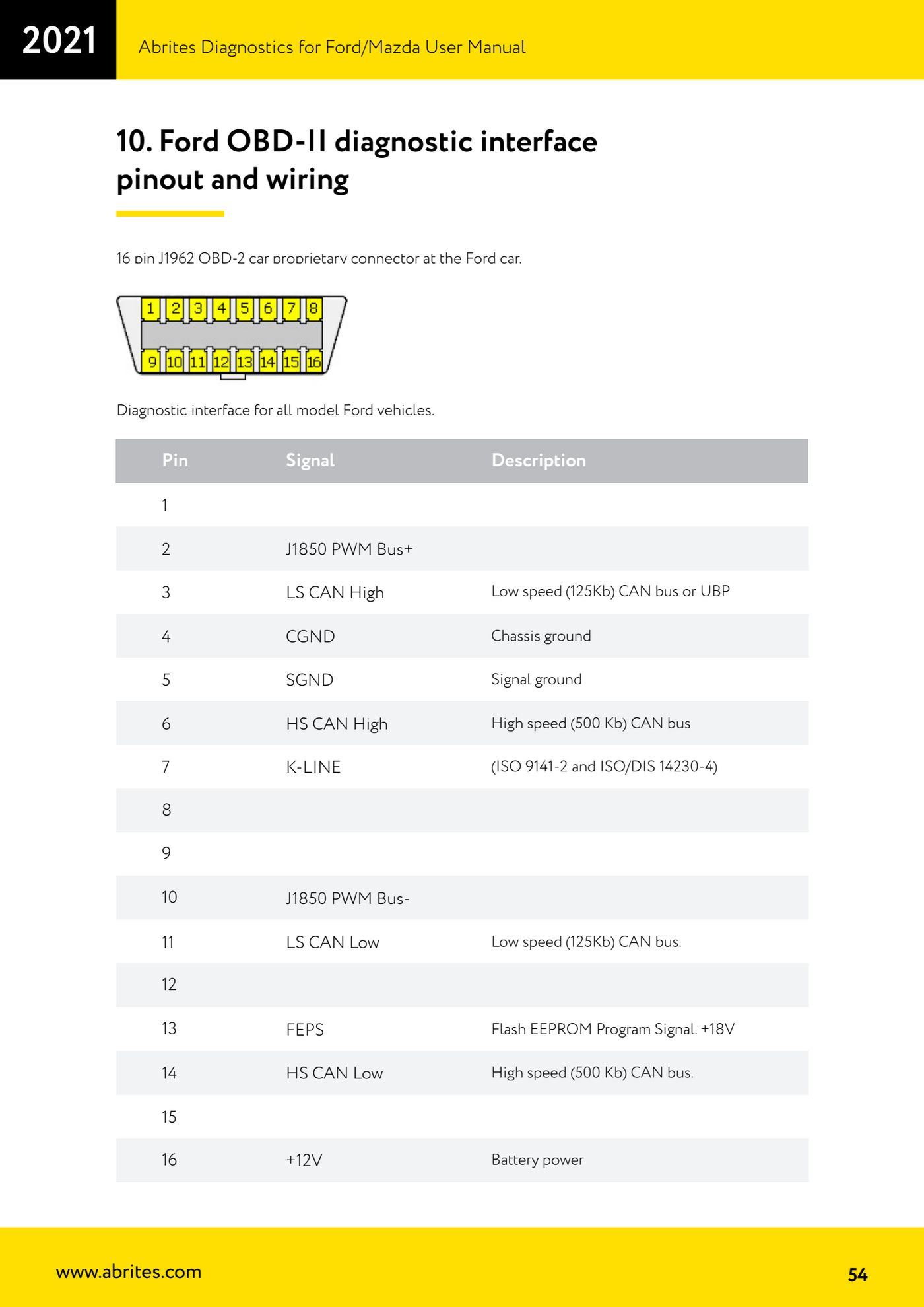
Signal layout of the 16-pin J1962 OBD-II diagnostic socket on Ford vehicles, plus a summary of the protocols used by year of production. Use it to check the wiring and to work out which line the module should answer on.
Required licences
- —
Hardware / cables

⚠ WarningPin 13 carries the FEPS signal (Flash EEPROM Program Signal) at +18V: that is above battery voltage and must only be used where it is genuinely called for.
Procedure
- Identify the socket: proprietary 16-pin OBD-2 J1962 connector, the diagnostic interface for all Ford models.
- Pin 2: J1850 PWM Bus+.
- Pin 3: LS CAN High - low speed CAN bus (125 Kb) or UBP.
- Pin 4: CGND - chassis ground.
- Pin 5: SGND - signal ground.
- Pin 6: HS CAN High - high speed CAN bus (500 Kb).
- Pin 7: K-LINE (ISO 9141-2 and ISO/DIS 14230-4).
- Pin 11: LS CAN Low - low speed CAN bus (125 Kb).
- Pin 16: +12V - battery feed.
- Pin 10: J1850 PWM Bus-.
- Pin 14: HS CAN Low - high speed CAN bus (500 Kb).
- Pin 13: FEPS - Flash EEPROM Program Signal, +18V.
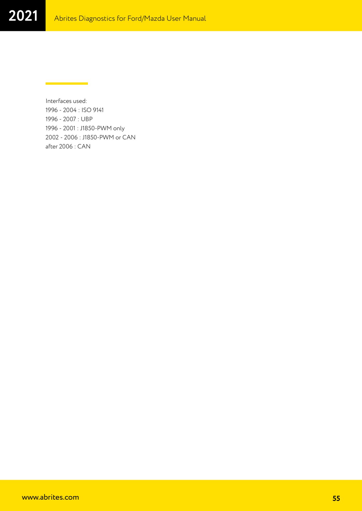
- Check the protocol against the year: 1996-2004 ISO 9141; 1996-2007 UBP; 1996-2001 J1850-PWM only; 2002-2006 J1850-PWM or CAN; after 2006 CAN.
Reference screenshots
Source: Manuale Ford/Mazda, parte 2 di 2, cap. 10 Ford OBD-II diagnostic interface pinout and wiring (p.54-55) · ⏱ estimated time 10 min
← All Abrites guides Hardware catalogue
More guides Ford/Mazda
- Starting Abrites Diagnostics for Ford/Mazda: vehicle context and ECU scanning ("Scan all")
- ECU identification, DTC read/clear and Live Data on Ford/Mazda
- Getting to the Ford/Mazda "Special Functions": Memory Read/Write and Key Learning
- PATS Key Learning: adding keys on Ford/Mazda (including with the alarm triggered)
- Key programming on Mazda CX-30 and Mazda 3 from 2019 with special function MZ001
- Ford key programming from 2021 (F-150, Maverick, Mustang Mach-E, Transit): incode from the outcode or bench read of the BCM with the ZN085
- PATS Erase All Keys: erasing all keys from the Ford/Mazda PATS memory
- PATS Initialization: matching the PCM to the instrument cluster (IPC/HEC), BCM or FIP on Ford/Mazda
- Spare Key Programming and Unlimited Key Mode: enabling/disabling Ford/Mazda key programming
- PATS OUT/IN code calculator for Ford/Mazda IDS (SINGLE xx40 and DOUBLE xx44 outcodes)
- VID block (Vehicle Identification Data) in the Ford/Mazda PCM: reading and configuring parameters
- Supported protocols and OBDII pins on Ford/Mazda: HS-CAN, MS-CAN, K-Line and J1850 PWM