
Chip-Tools
ZN073 BDM adapter pinout: connector A standard 10-pin and connector B Bosch EDC 14-pin
Strumenti
Interface Classic
Hardware / Connections
Advanced
⏱ 15 min
5 steps
Pin layout for the two BDM connectors on the ZN073: connector A is the standard 10-pin BDM, connector B is the 14-pin Bosch EDC BDM. Use it to build or check the flat cable before you hook up to the ECU.
Required licences
- —
Hardware / cables
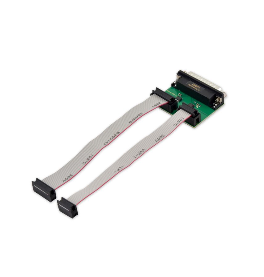 ZN073 BDM ECU Programmer
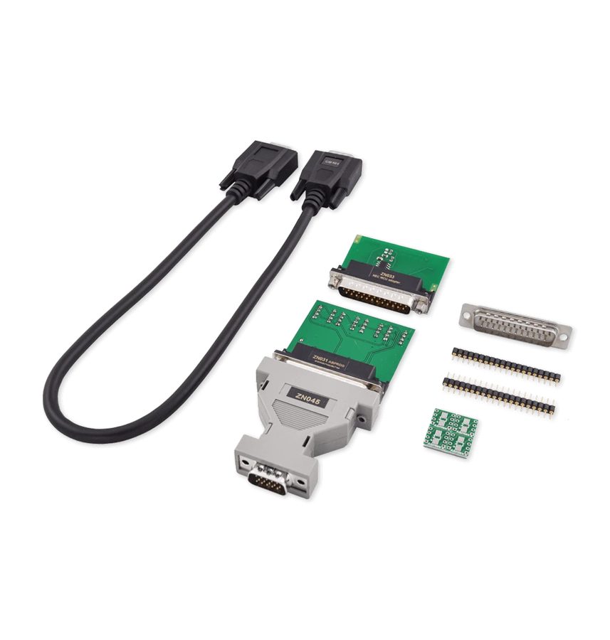 ZN045 programmatore ABPROG
- cavo flat (ribbon)
- header PCB doppia fila passo 1.27 mm
⚠ WarningMiswiring the BDM cable can permanently damage the adapter and/or the ECU: check it pin by pin before applying power.
Procedure
- Connector A - standard 10-pin BDM: Pin 1 = VFLS 0, Pin 2 = Not Connected, Pin 3 = GND, Pin 4 = DSCK, Pin 5 = GND, Pin 6 = VFLS 1, Pin 7 = HRESET, Pin 8 = DSDI, Pin 9 = VCC, Pin 10 = DSDO.
- Connector B - 14-pin Bosch EDC BDM: Pin 1 = HRESET, Pin 2 = Not Connected, Pin 3 = DSCK, Pin 4 = DSDI, Pin 5 = Not Connected, Pin 6 = VCC, Pin 7 = Not Connected, Pin 8 = DSDO, Pin 9 = Not Connected, Pin 10 = GND, Pin 11 = VFLS 1, Pin 12 = Not Connected, Pin 13 = VFLS 0, Pin 14 = Not Connected.
- Make up the flat cable respecting pin 1 orientation at both ends and check continuity with a multimeter before connecting the ECU.
- Remember that a double-row 14-pin header with 1.27 mm pitch has to be soldered to the ECU's test points.
- Connect the flat cable to the ZN073 adapter first, then the ZN073 to the ZN045 and the ZN045 to the AVDI, and only after that power the system following the sequence laid down for BDM.
Reference screenshots
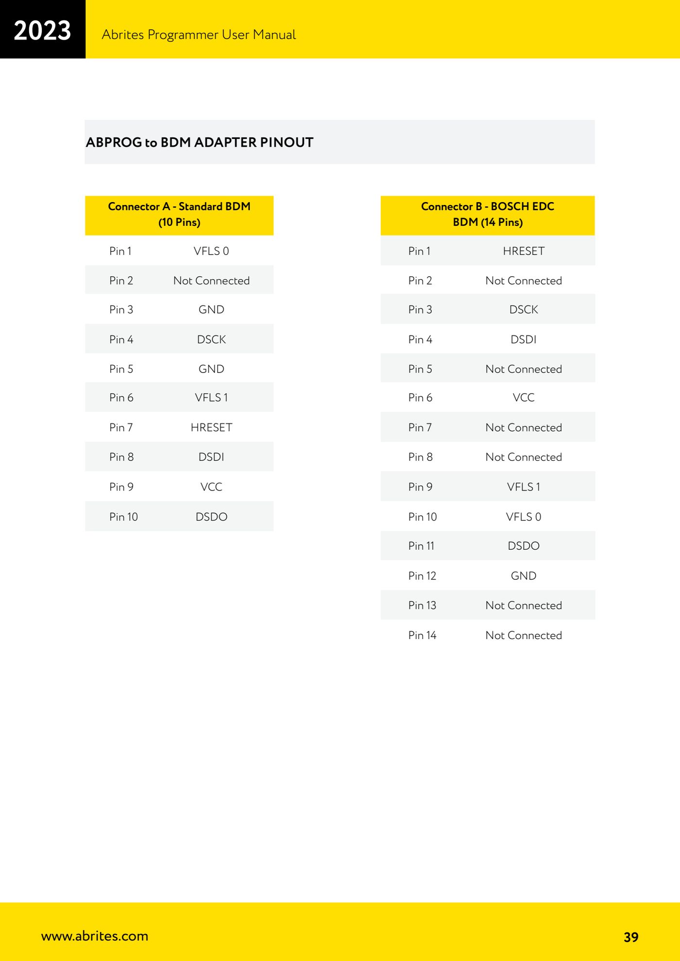
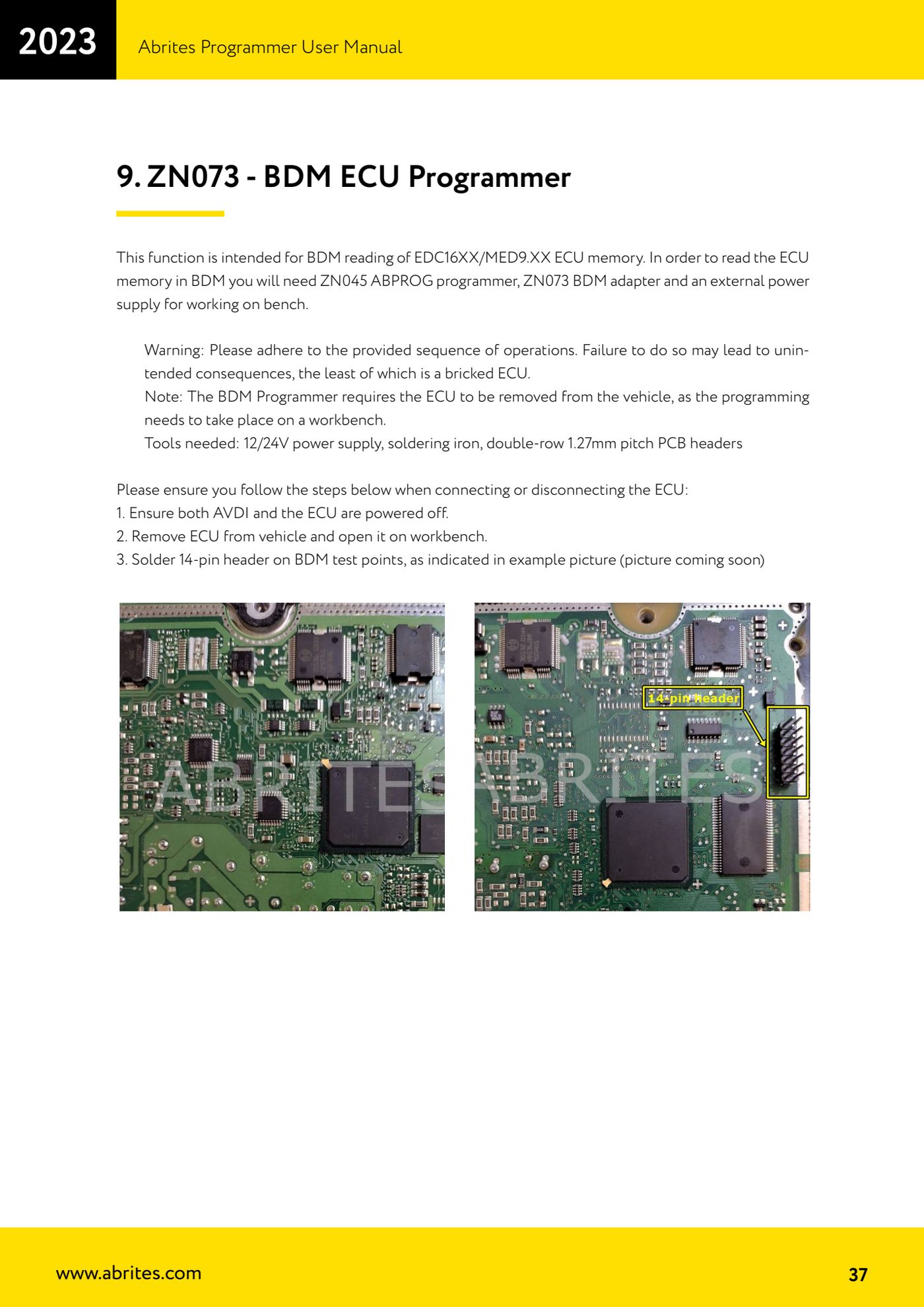
Source: Manuale Abrites Programmer, cap. 9 - ABPROG to BDM adapter pinout (p.37, p.39) · ⏱ estimated time 15 min
← All Abrites guides Hardware catalogue
More guides Strumenti
- ABPROG ZN030: what's in the set, hooking it up to the AVDI and starting the Classic software
- Reading and writing SPI, I2C and Microwire EEPROMs with ABPROG and the ZN031/ZN035 adapter
- Erasing and reprogramming M35080VP / M35080V6 incremental EEPROMs with ABPROG
- Wiring an SPI EEPROM straight to the ABPROG DB25 without the ZN031 adapter
- Mercedes-Benz IR keys: reading the SSID, erasing and programming the NEC with ZN032 / ZN033
- Renewing used keys (HITAG/PCF) with the ZN046 adapter and ABPROG
- Solder points on key PCBs for the ZN046 and list of keys supported for renewal
- Reading the EWS3 dump on BMW E46/E39/E53 and others with the ZN055 adapter
- Reading the EEPROM on BMW F-Series FEM/BDC without desoldering, using the ZN057 extension
- Reading and writing NEC V850ES MCUs with the ZN078 adapter and ABPROG
- ABPROG DB25 pinout: building your own ZN046, ZN058, ZN078 and ZN086 adapters
- Reading the immobiliser from a Renault X95 BCM (and Audi BCM) with ABPROG and direct wiring