
Chip-Tools
CB403 extended cable set for the ZN151: HD15 pinout, wire colours and supplied probes
Strumenti
Interface Classic
Hardware / Connections
Medium
⏱ 15 min
7 steps
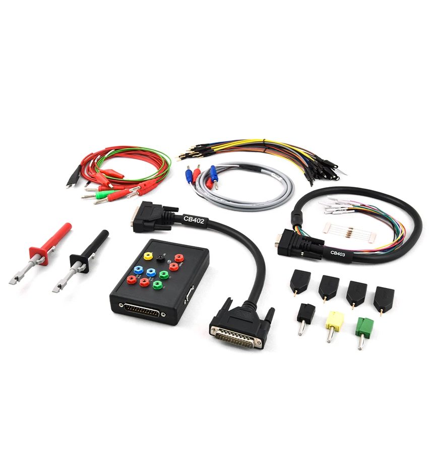
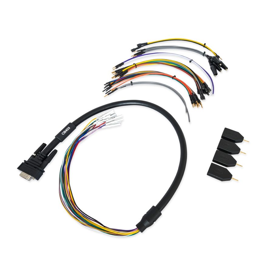
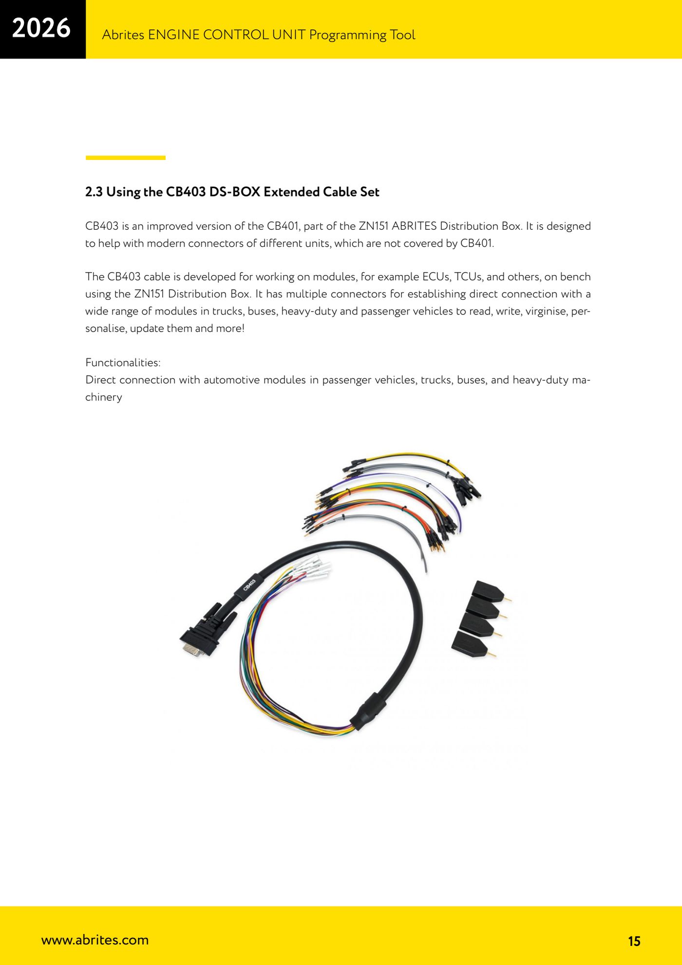
The CB403 is the improved version of the CB401 supplied with the ZN151: it's for connecting to the modern connectors on ECU, TCU and other modules the CB401 doesn't cover, on cars, trucks, buses and heavy vehicles, to read, write, virginise, personalise and update units on the bench.

Procedure
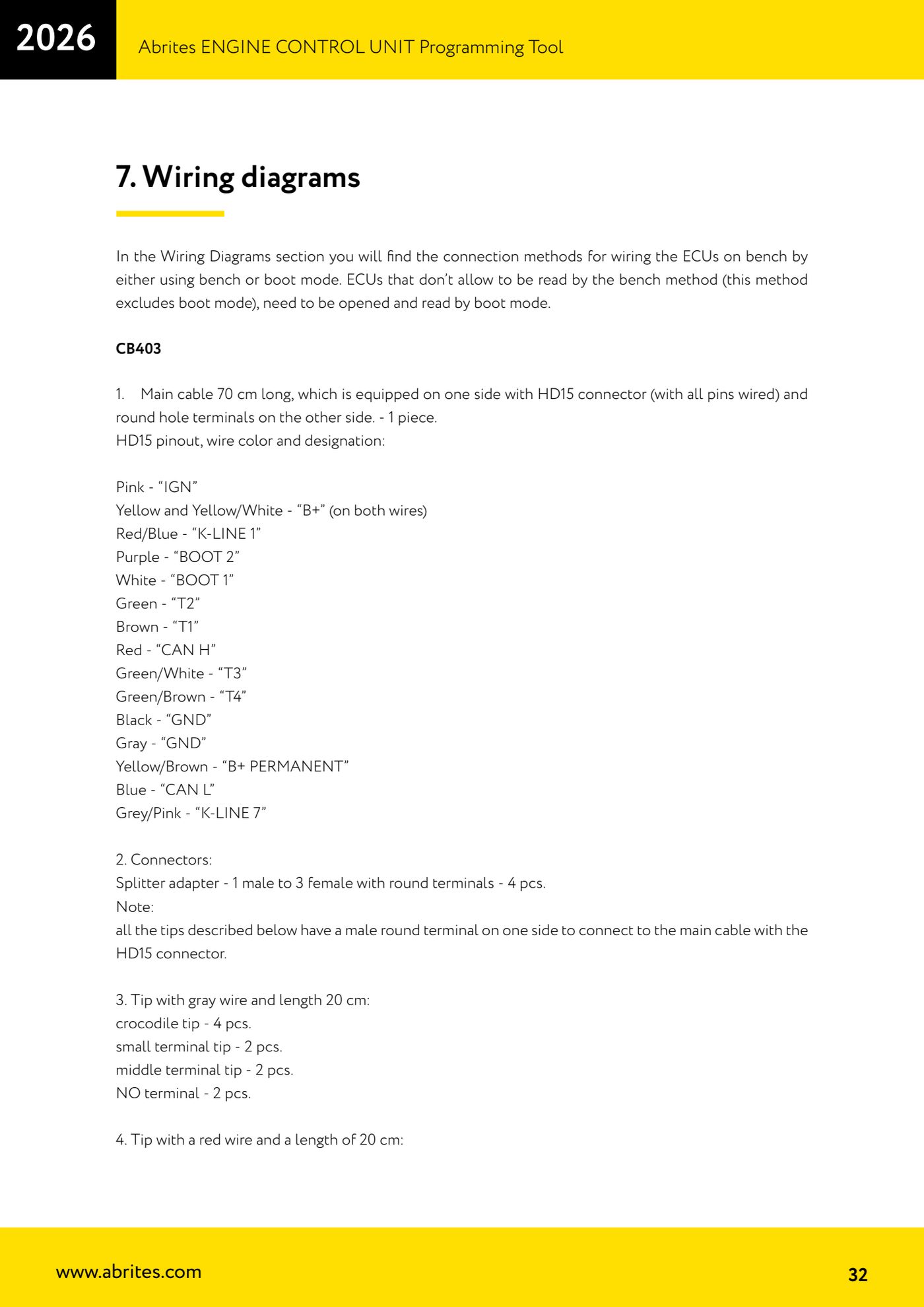
- Connect the HD15 connector of the main cable (70 cm, all pins wired) to the ZN151 DS Box; the other end has round female terminals to plug the probes into.
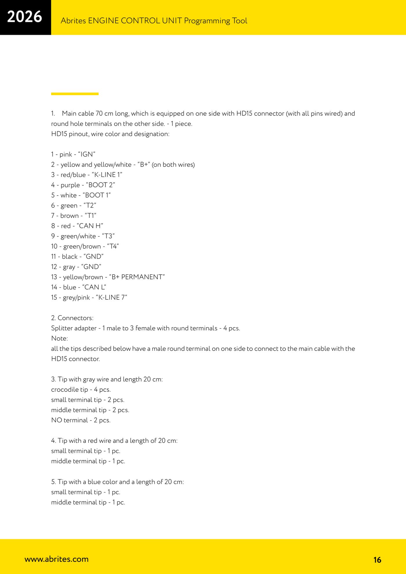
- Use this HD15 pinout to know what you have in hand: pin 1 pink = "IGN"; pin 2 yellow and yellow/white = "B+" (on both wires); pin 3 red/blue = "K-LINE 1"; pin 4 purple = "BOOT 2"; pin 5 white = "BOOT 1"; pin 6 green = "T2"; pin 7 brown = "T1"; pin 8 red = "CAN H".
- Rest of the pinout: pin 9 green/white = "T3"; pin 10 green/brown = "T4"; pin 11 black = "GND"; pin 12 grey = "GND"; pin 13 yellow/brown = "B+ PERMANENT"; pin 14 blue = "CAN L"; pin 15 grey/pink = "K-LINE 7".
- If you need to take the same signal to several points, use the splitters supplied: 4 adapters, 1 male to 3 females with round terminals.
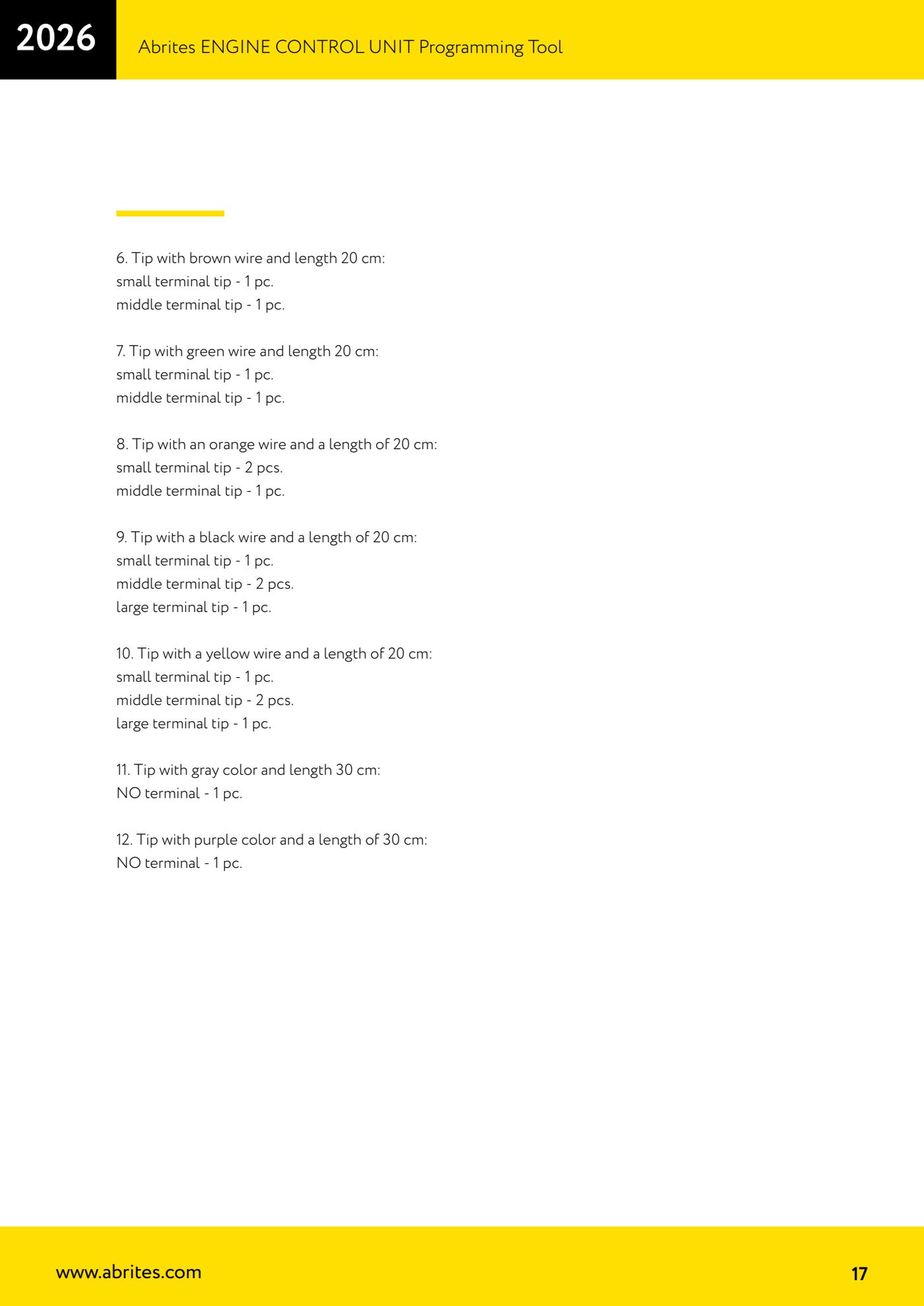
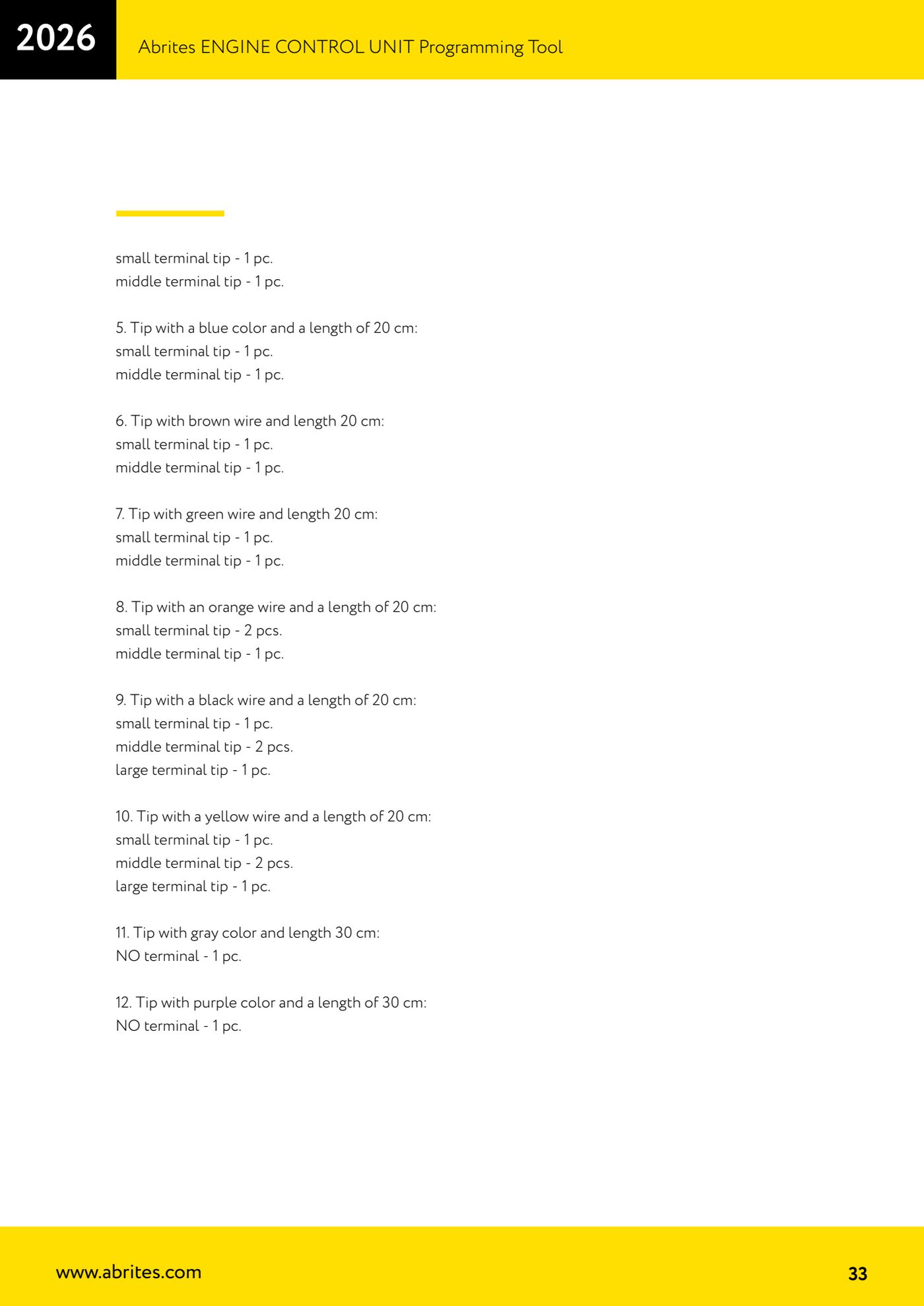
- Pick the right probes (they all have a round male terminal to plug into the HD15 main cable): grey 20 cm with 4 crocodile clips, 2 small probes, 2 medium and 2 with no terminal; red 20 cm with 1 small and 1 medium; blue 20 cm with 1 small and 1 medium; brown 20 cm with 1 small and 1 medium; green 20 cm with 1 small and 1 medium.
- Remaining probes: orange 20 cm with 2 small and 1 medium; black 20 cm with 1 small, 2 medium and 1 large; yellow 20 cm with 1 small, 2 medium and 1 large; grey 30 cm with no terminal (1 pc); purple 30 cm with no terminal (1 pc).
- Wire the ECU following the PIN OUT diagrams in the manual, always starting from GND, and only then feed the ZN151 with external 12V.
Reference screenshots
Source: Manuale ECU Programming Tool, parte 1 di 3, cap. 2.3 e 7 (p.15-17, 32-33) · ⏱ estimated time 15 min
← All Abrites guides Hardware catalogue
More guides Strumenti
- ABPROG ZN030: what's in the set, hooking it up to the AVDI and starting the Classic software
- Reading and writing SPI, I2C and Microwire EEPROMs with ABPROG and the ZN031/ZN035 adapter
- Erasing and reprogramming M35080VP / M35080V6 incremental EEPROMs with ABPROG
- Wiring an SPI EEPROM straight to the ABPROG DB25 without the ZN031 adapter
- Mercedes-Benz IR keys: reading the SSID, erasing and programming the NEC with ZN032 / ZN033
- Renewing used keys (HITAG/PCF) with the ZN046 adapter and ABPROG
- Solder points on key PCBs for the ZN046 and list of keys supported for renewal
- Reading the EWS3 dump on BMW E46/E39/E53 and others with the ZN055 adapter
- Reading the EEPROM on BMW F-Series FEM/BDC without desoldering, using the ZN057 extension
- Reading and writing NEC V850ES MCUs with the ZN078 adapter and ABPROG
- ABPROG DB25 pinout: building your own ZN046, ZN058, ZN078 and ZN086 adapters
- Reading the immobiliser from a Renault X95 BCM (and Audi BCM) with ABPROG and direct wiring