
Chip-Tools
Bosch EDC17C10 TC1796/TC1797 (Citroen, Peugeot, Ford): BSL connection and CAN pins for password reading
Strumenti
Interface Classic
Hardware / Connections
Advanced
⏱ 30-60 min
8 steps
The EDC17C10 is one of the few ECUs for which the manual gives explicit pin numbers: when reading in boot mode, CAN has to go to different pins than usual. You need this when reading an EDC17C10 from a Citroen, Peugeot or Ford and you have to pull the password.
Required licences
- —
Hardware / cables

⚠ WarningImportant note from the manual: when reading the ECU in boot mode, the CAN connection for password reading is CAN HIGH (red) on pin 38 and CAN LOW (blue) on pin 50. If you use the ECU's standard CAN pins the password will not be read. Watch the variant as well: the manual gives two separate diagrams, Variant 1 and Variant 2, for the same EDC17C10 designation.
Procedure
- Identify the ECU: Bosch EDC17C10 label, TC1796 or TC1797 microcontroller, Citroen, Peugeot or Ford application.
- Compare the board against the two drawings in the manual and establish whether you have Variant 1 or Variant 2: the two layouts have different wiring diagrams.
- For Variant 1 build the base connection as per the drawing, then add the "BSL connection" shown on the same page to bring the ECU into boot mode.
- For reading in boot mode, wire CAN as the manual states: CAN HIGH, red wire, to pin 38; CAN LOW, blue wire, to pin 50.
- Re-check the pin numbering on the connector before applying power: CAN swapped over or landed on an adjacent pin will kill communication.
- Power up the ECU and connect the AVDI, then start the read from the software with the ECU in boot mode.
- Save the file you read out and the recovered password before you attempt any write operation.
- If the ECU does not respond, make sure you have not used the other variant's diagram and re-check the two CAN wires on pins 38 and 50.
Reference screenshots
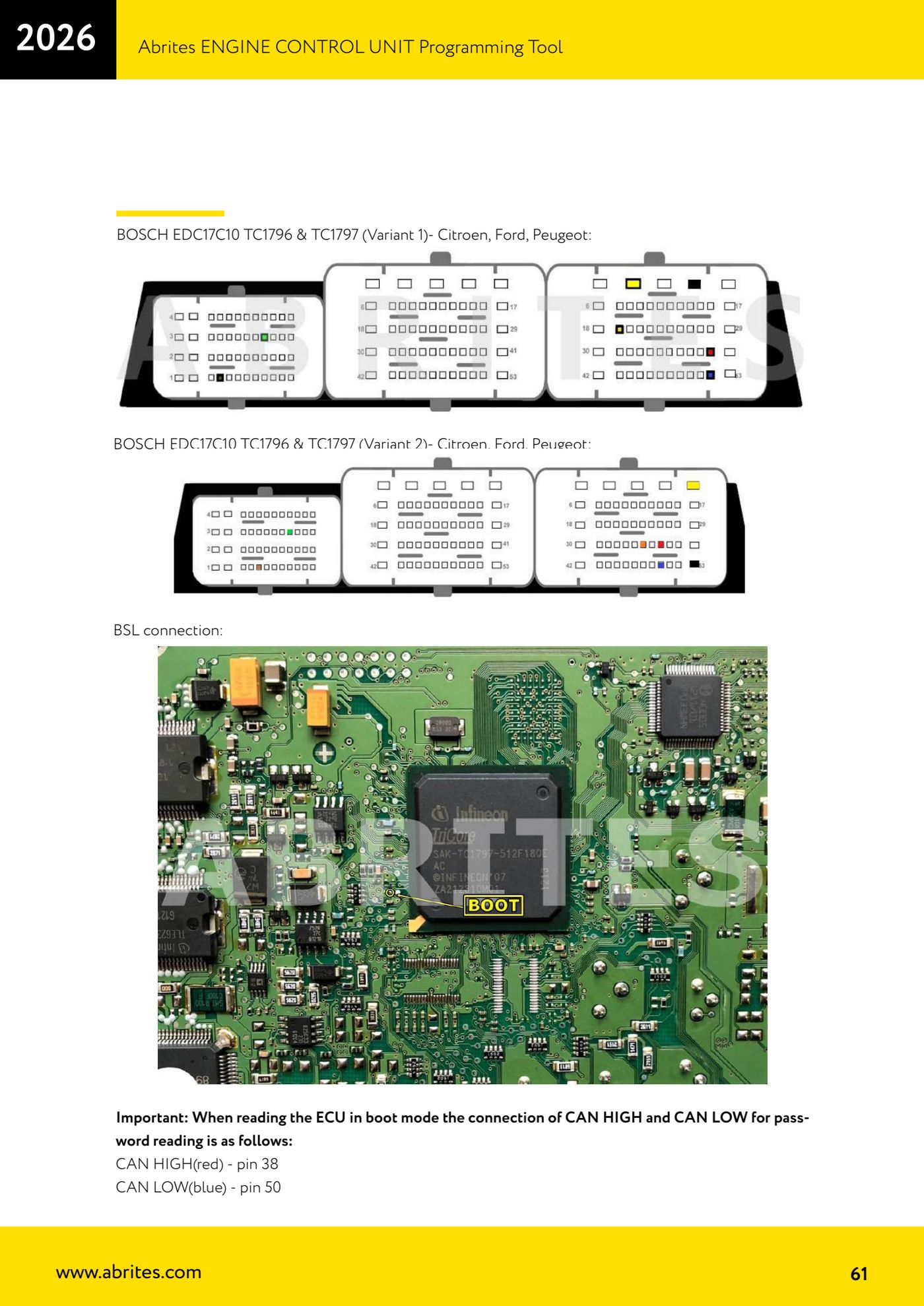
Source: Manuale ECU Programming Tool, parte 2 di 3, sezione BOSCH EDC17C10 (p.61) · ⏱ estimated time 30-60 min
← All Abrites guides Hardware catalogue
More guides Strumenti
- ABPROG ZN030: what's in the set, hooking it up to the AVDI and starting the Classic software
- Reading and writing SPI, I2C and Microwire EEPROMs with ABPROG and the ZN031/ZN035 adapter
- Erasing and reprogramming M35080VP / M35080V6 incremental EEPROMs with ABPROG
- Wiring an SPI EEPROM straight to the ABPROG DB25 without the ZN031 adapter
- Mercedes-Benz IR keys: reading the SSID, erasing and programming the NEC with ZN032 / ZN033
- Renewing used keys (HITAG/PCF) with the ZN046 adapter and ABPROG
- Solder points on key PCBs for the ZN046 and list of keys supported for renewal
- Reading the EWS3 dump on BMW E46/E39/E53 and others with the ZN055 adapter
- Reading the EEPROM on BMW F-Series FEM/BDC without desoldering, using the ZN057 extension
- Reading and writing NEC V850ES MCUs with the ZN078 adapter and ABPROG
- ABPROG DB25 pinout: building your own ZN046, ZN058, ZN078 and ZN086 adapters
- Reading the immobiliser from a Renault X95 BCM (and Audi BCM) with ABPROG and direct wiring