
Chip-Tools
Bench and BSL connections for Bosch MED17.7.x / MED17.8.x / MEVD17.2.x (Mercedes, BMW, Mini, Jaguar, Land Rover, Infiniti)
Strumenti
Interface Classic
Hardware / Connections
Advanced
⏱ 30-60 min
7 steps
Bench connection diagrams for reading and writing the Bosch MED17.7.x, MED17.8.x and MEVD17.2.x ECUs with the ECU Programming Tool. The manual separates two types of wiring: the bench CAN connection for reading the password in boot mode, and the actual "BSL connection", which on some variants is the only way to read the microcontroller.
Required licences
- —
Hardware / cables
 AVDI
AVDI- alimentatore da banco 12V
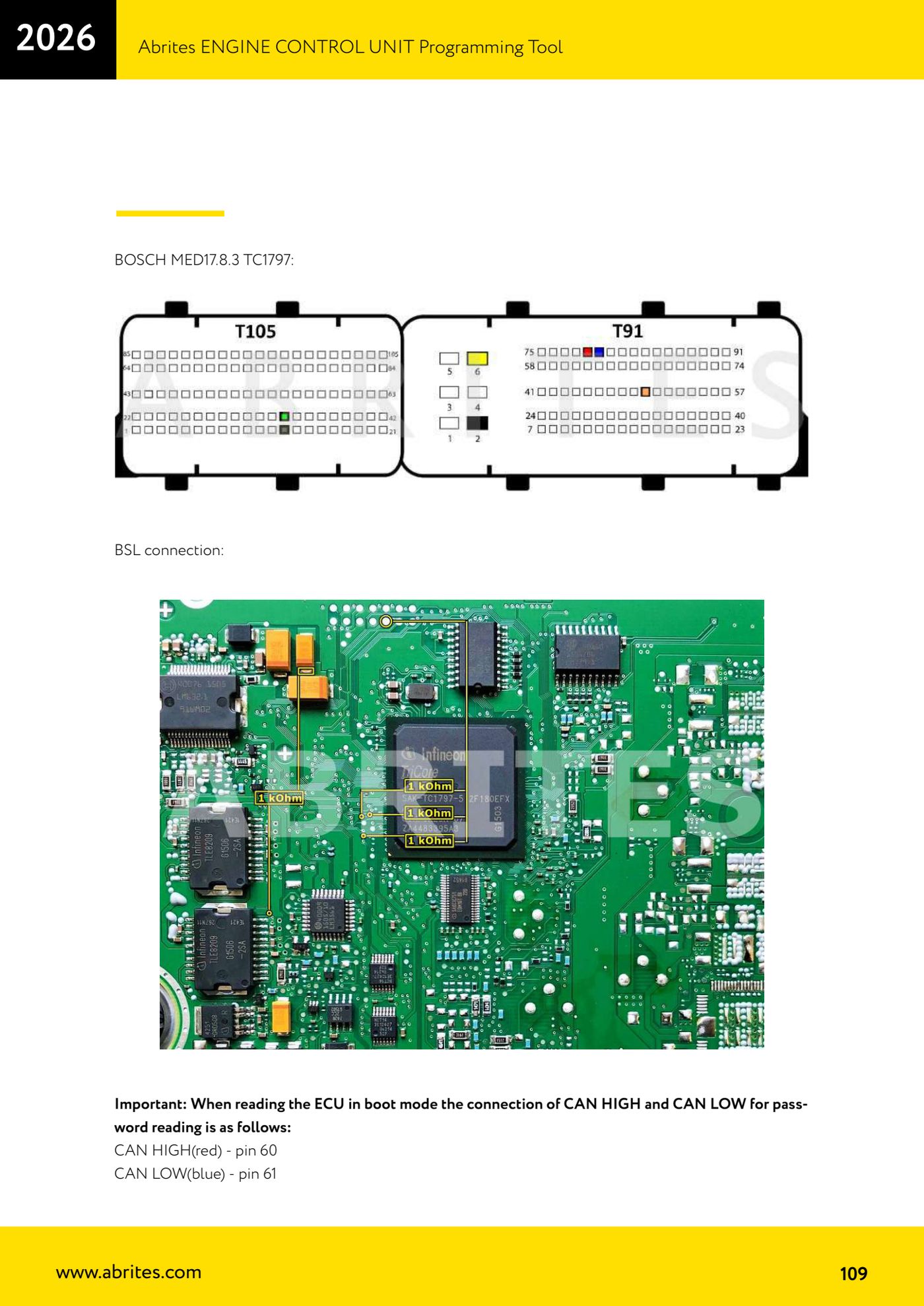
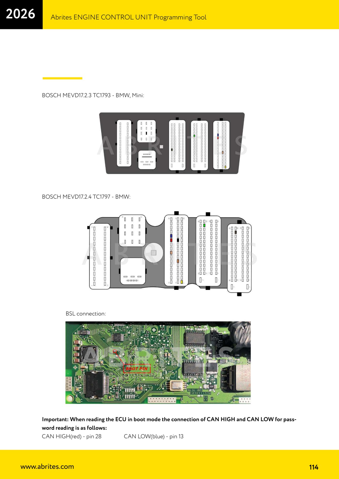
⚠ WarningIn boot mode the CAN pins change from family to family: on the MED17.8.3 TC1797 the password is read with CAN HIGH (red wire) on pin 60 and CAN LOW (blue wire) on pin 61, whereas on the MEVD17.2.3 TC1793 it is CAN HIGH pin 28 and CAN LOW pin 13. Never reuse another variant's pinout: CAN swapped over or a wire on the wrong pin can damage the ECU.
Procedure
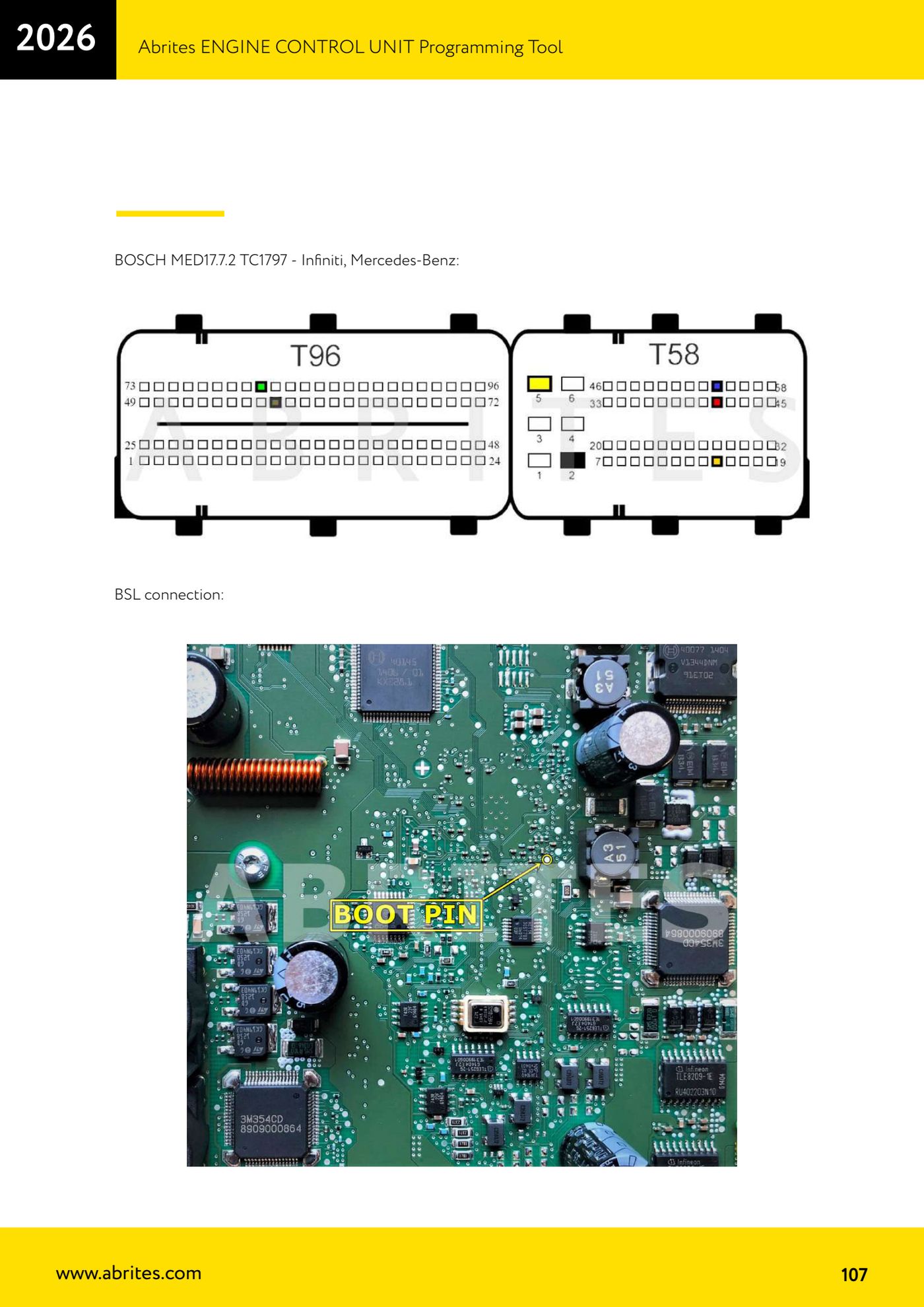
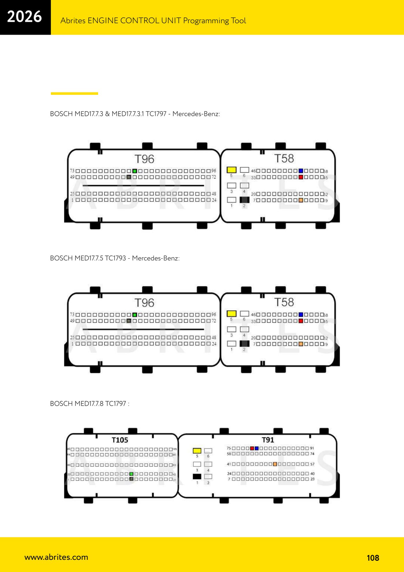
- Identify precisely the Bosch designation printed on the ECU label (for example MED17.7.2, MED17.7.3.1, MED17.7.5, MED17.7.8, MED17.8.3, MED17.8.31, MEVD17.2.3 ... MEVD17.2.P) and the microcontroller (TC1793 or TC1797): every variant has its own dedicated diagram in the manual.
- Open the ECU and set it on an insulating, antistatic surface with the board accessible from both sides: the BSL points and the CAN points to hook onto are found on the connector pins and on the board's test points.
- Bring bench power to the ECU (12V+ and GND) following the diagram on the page for your variant, and check current draw before connecting any data line.
- For password reading in boot mode, connect the two CAN lines as specified for your variant: on the MED17.8.3 TC1797, CAN HIGH (red) on pin 60 and CAN LOW (blue) on pin 61; on the MEVD17.2.3 TC1793, CAN HIGH (red) on pin 28 and CAN LOW (blue) on pin 13.
- Where the manual also gives a "BSL connection" entry (MED17.7.2 TC1797, MED17.8.3 TC1797, MEVD17.2.4 TC1797, MEVD17.2.G TC1797), additionally make the BSL jumper shown in the photo on that page: without that point the microcontroller will not enter boot mode.
- Connect the AVDI to the wired-up set, start the ECU Programming Tool and select the matching ECU; do a full read (backup) first and only then any writing.
- If the password read fails, before redoing the loom check you have not swapped red and blue: it is the most frequent mistake, because the CAN pins change between MEVD17.2.x variants even though the connectors look identical.
Reference screenshots
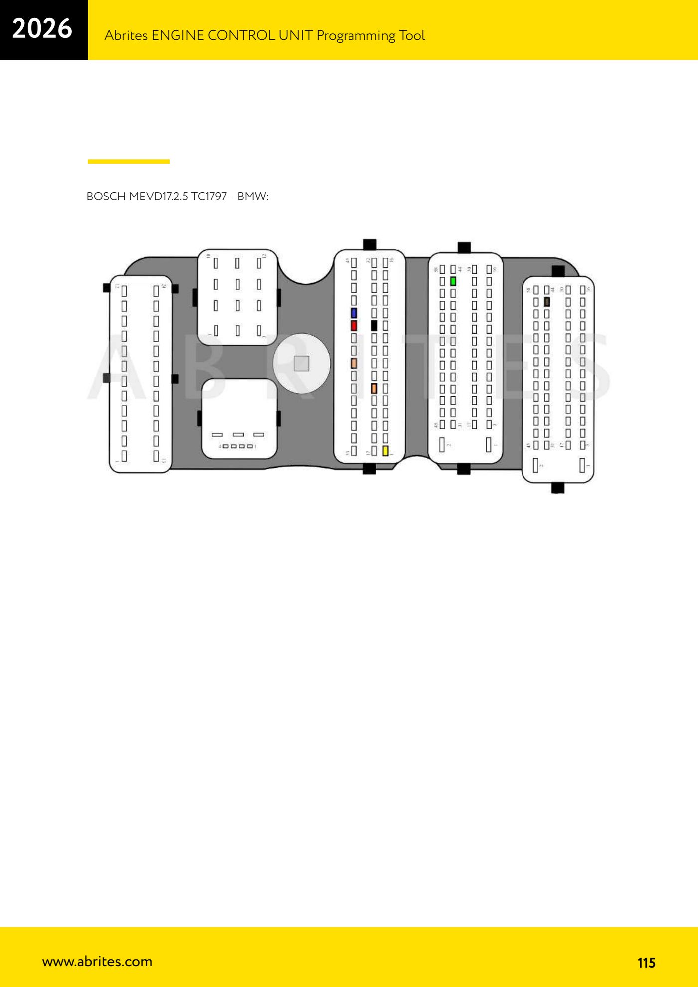
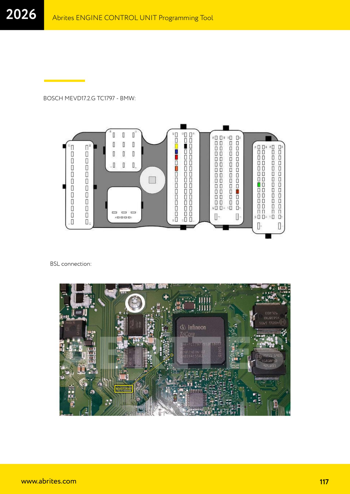
Source: Manuale ECU Programming Tool, parte 3 di 3, sezione collegamenti ECU (p.107-118) · ⏱ estimated time 30-60 min
← All Abrites guides Hardware catalogue
More guides Strumenti
- ABPROG ZN030: what's in the set, hooking it up to the AVDI and starting the Classic software
- Reading and writing SPI, I2C and Microwire EEPROMs with ABPROG and the ZN031/ZN035 adapter
- Erasing and reprogramming M35080VP / M35080V6 incremental EEPROMs with ABPROG
- Wiring an SPI EEPROM straight to the ABPROG DB25 without the ZN031 adapter
- Mercedes-Benz IR keys: reading the SSID, erasing and programming the NEC with ZN032 / ZN033
- Renewing used keys (HITAG/PCF) with the ZN046 adapter and ABPROG
- Solder points on key PCBs for the ZN046 and list of keys supported for renewal
- Reading the EWS3 dump on BMW E46/E39/E53 and others with the ZN055 adapter
- Reading the EEPROM on BMW F-Series FEM/BDC without desoldering, using the ZN057 extension
- Reading and writing NEC V850ES MCUs with the ZN078 adapter and ABPROG
- ABPROG DB25 pinout: building your own ZN046, ZN058, ZN078 and ZN086 adapters
- Reading the immobiliser from a Renault X95 BCM (and Audi BCM) with ABPROG and direct wiring