
Chip-Tools
KP002 on the bench on JLR L8B2 and JPLA BCMs: pinout, wiring and LED states
JLR
Interface Classic
Hardware / Connections
Advanced
⏱ varies (up to 72 hours)
8 steps
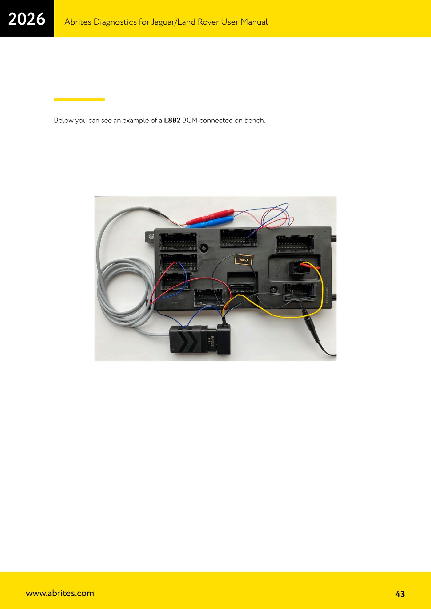
Bench connection of the KP002 directly onto the BCM pins, when you are not working in the car. Here you have the exact pinout for the L8B2 and JPLA BCMs and how to read the device LED states.
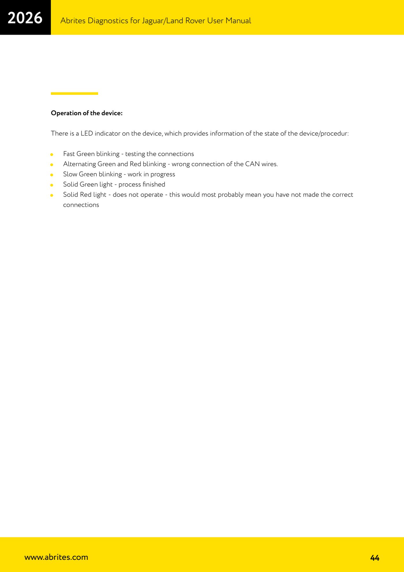
⚠ WarningA reversed or wrong CAN connection shows up on the LED: alternating green/red flashing means the CAN wires are wrongly connected, steady red means the device is not operating because of incorrect connections. Check the wiring before you leave the bench: the procedure can take up to 72 hours.
Procedure
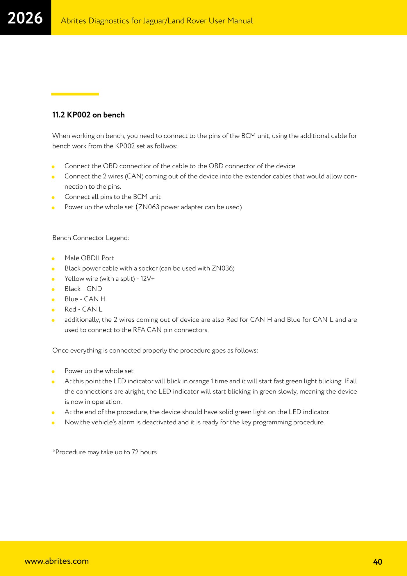
- Prepare the bench cable set included in the KP002 kit and connect the OBD connector of the cable to the OBD connector on the device.
- Connect the 2 CAN wires coming out of the device to the extension leads that let you tap the BCM pins: red = CAN H, blue = CAN L, to be taken to the RFA CAN pins.
- Bench connector legend: male OBDII connector; black power cable with socket (usable with ZN036); yellow wire (with a split) = 12V+; black = GND; blue = CAN L; red = CAN H.
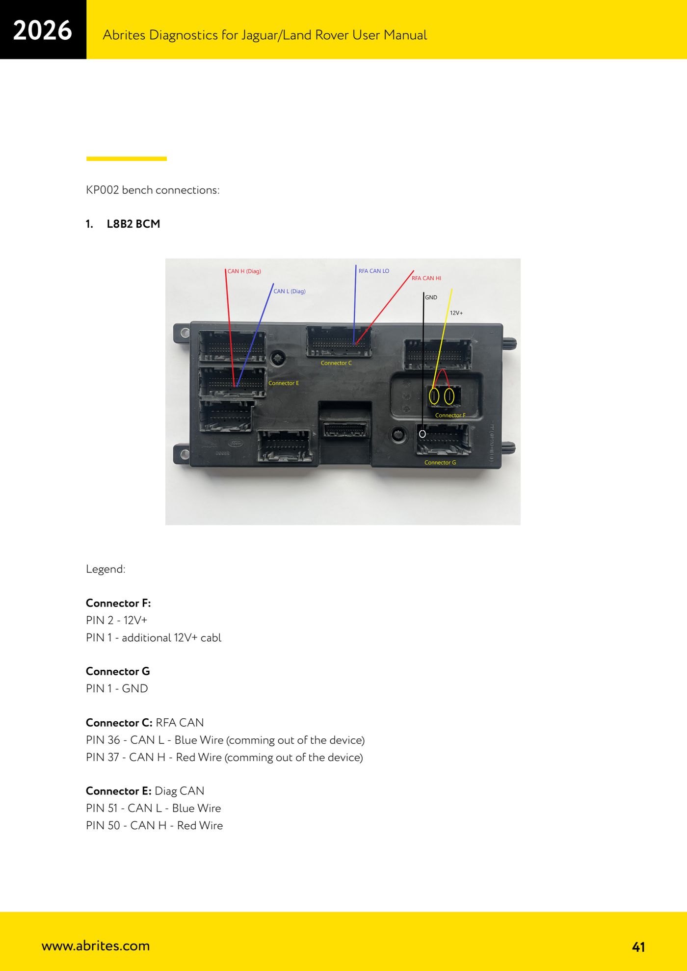
- On the L8B2 BCM wire it as follows: connector F PIN 2 = 12V+ and PIN 1 = additional 12V+; connector G PIN 1 = GND; connector C (RFA CAN) PIN 36 = CAN L, device blue wire, and PIN 37 = CAN H, device red wire; connector E (Diag CAN) PIN 51 = CAN L blue wire and PIN 50 = CAN H red wire.
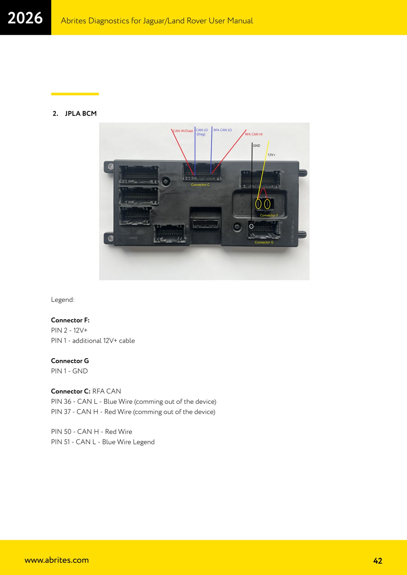
- On the JPLA BCM wire it as follows: connector F PIN 2 = 12V+ and PIN 1 = additional 12V+; connector G PIN 1 = GND; connector C (RFA CAN) PIN 36 = CAN L, device blue wire, and PIN 37 = CAN H, device red wire; PIN 50 = CAN H red wire and PIN 51 = CAN L blue wire.
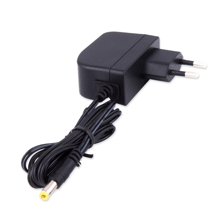
- Power up the whole set (you can use the ZN063 power supply).
- Check the LED: one orange flash, then fast green flashing (connection test); if everything is correct it changes to slow green flashing, meaning work in progress.
- Wait for steady green: procedure finished, alarm off and BCM unlocked. Refit the BCM to the vehicle and go ahead with key programming.
Reference screenshots
Source: Manuale Jaguar/Land Rover, cap. 11.2 (p.40-44) · ⏱ estimated time varies (up to 72 hours)
← All Abrites guides Hardware catalogue
More guides JLR
- Module scan, DTC reading and service functions on Jaguar/Land Rover with AVDI
- Key Learning / Module Initialization via OBDII on JLR 2012-2018 (unlocked KVM/RFA)
- Key Duplicator on JLR 2018+ with PROTAG and TA54/TA56/TA66/TA67 keys
- JLR 2018-2026 key programming from a 95128 BCM EEPROM dump (works with the alarm armed)
- JLR remote control synchronization after key programming (PROTAG)
- Resetting and reusing used Abrites TA54/TA56/TA66/TA67 keys for JLR (Abrites Key Reset)
- JLR cluster calibration: matching mileage after fitting a used control unit
- NV DATA and Flash on JLR: reading, saving and writing configuration and flash files for module replacement
- Immo Advanced JLR: writing transponder ID and secret key into the BCM for emergency start
- Fitting the Abrites EM015 UWB emulator on JLR: file preparation and wiring to the UWB antenna / KVM
- Abrites EM015 UWB emulator firmware update (EMUL update)
- JLR Dump tool: preparing the KVM flash (FK72, DPLA, HPLA) to program OEM keys