
Chip-Tools
Pinout and wire colors of the CB401 (DB15) and CB403 cables for FBS4 bench work
Mercedes
Interface New
Hardware / Connections
Medium
⏱ 10 min
8 steps
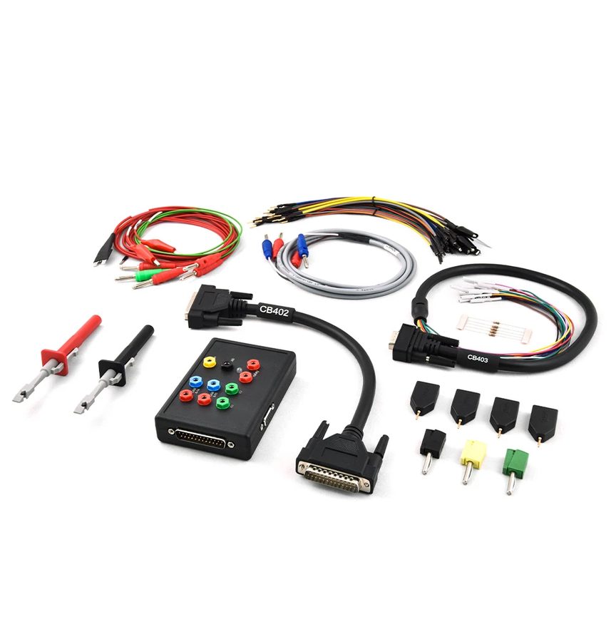
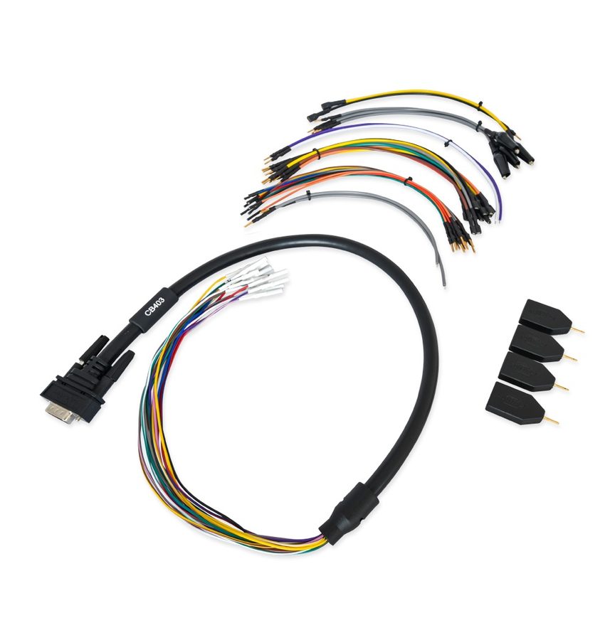
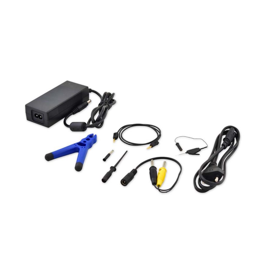
A quick reference to the colors and functions of the wires in the CB401 and CB403 cables used with the ZN051 DS Box to connect Mercedes FBS4 ECUs on the bench. You need it to read all the ECU diagrams in the manual correctly, since they use the CB401 colors.

Procedure
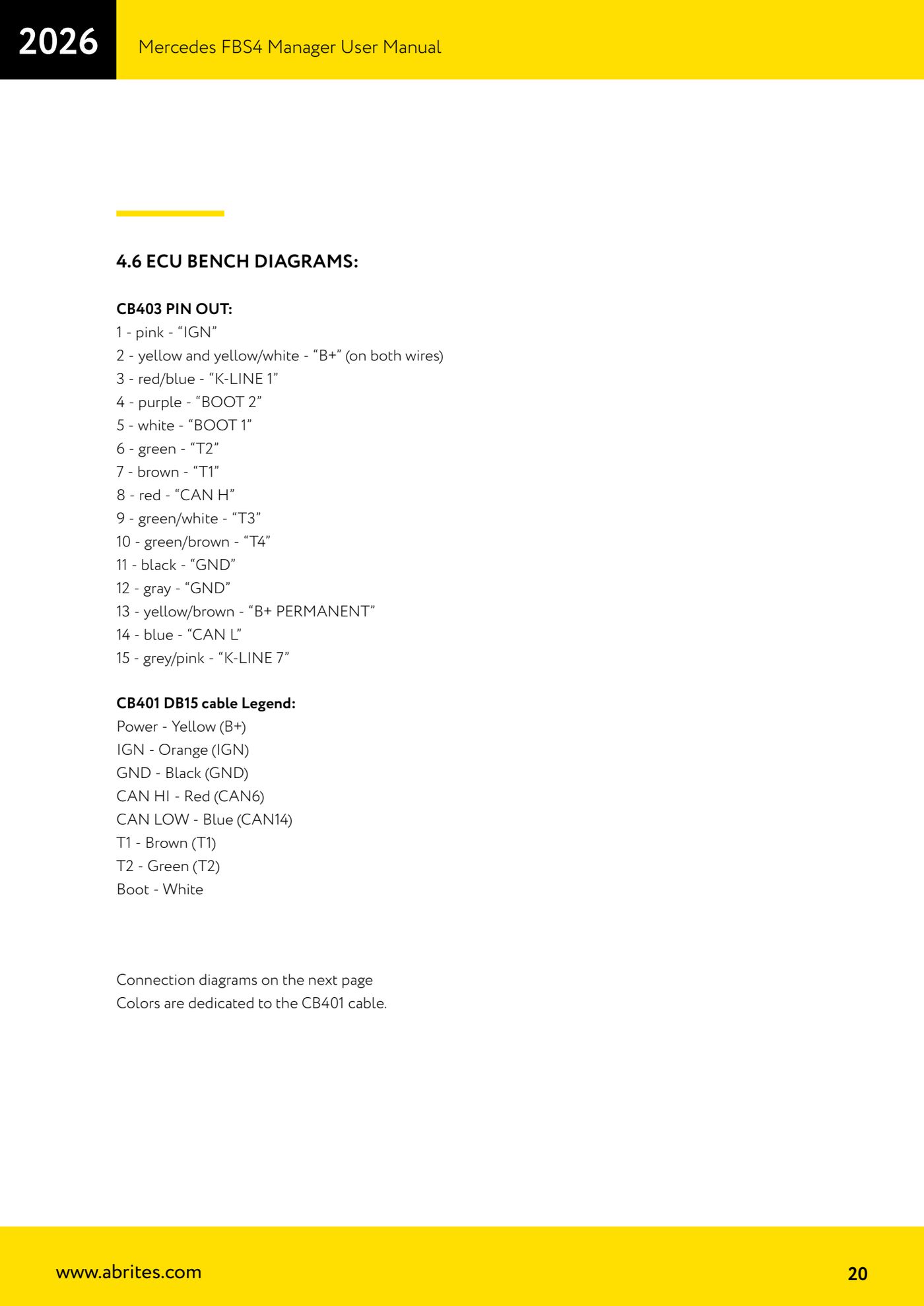
- CB403 - pin 1: pink wire = "IGN".
- CB403 - pin 2: yellow and yellow/white wire = "B+" (on both wires).
- CB403 - pin 3: red/blue = "K-LINE 1"; pin 4: purple = "BOOT 2"; pin 5: white = "BOOT 1".
- CB403 - pin 6: green = "T2"; pin 7: brown = "T1"; pin 9: green/white = "T3"; pin 10: green/brown = "T4".
- CB403 - pin 8: red = "CAN H"; pin 14: blue = "CAN L".
- CB403 - pin 11: black = "GND"; pin 12: grey = "GND"; pin 13: yellow/brown = "B+ PERMANENT"; pin 15: grey/pink = "K-LINE 7".
- CB401 (DB15 cable) - color key: power = yellow (B+); IGN = orange (IGN); ground = black (GND); CAN HI = red (CAN6); CAN LOW = blue (CAN14); T1 = brown (T1); T2 = green (T2); Boot = white.
- Remember that the colors shown in the wiring diagrams of the individual ECUs refer to the CB401 cable.
Reference screenshots
Source: Manuale Mercedes FBS4 Manager, parte 1 di 2, cap. 4.6 - ECU Bench Diagrams (p.20) · ⏱ estimated time 10 min
← All Abrites guides Hardware catalogue
More guides Mercedes
- Diagnostics and vehicle selection (VIN, chassis, over 1300 modules)
- Mercedes-Benz bus and truck diagnostics
- Mercedes Coding (VMAX, side sensors, parameters)
- Mercedes ECU Flashing (CFF files)
- Mercedes FBS4 Manager (722.9 and CRD3 renew, VIN change)
- Smart Functions (DPF mileage reset, DPF ash, VIM, seat belt alarm, sun roof, 360° cameras)
- FBS4 odometer correction with MN030 + emulators (EM008/EM014/EM018)
- Exhaust flaps — exhaust valve control
- CPC Torque limiter — torque limit
- VMax calibration — speed limiter
- Speed Limit Calibration — eVito 447 (electric)
- Mercedes AdBlue Reset: resetting the AdBlue system after component replacement or the remaining mileage warning