
Chip-Tools
Bench wiring diagrams for Bosch MED17 / MED40 / MED177 / MED41 ECUs (T96, T58, T105, T91 pins)
Mercedes
Interface New
Hardware / Connections
Advanced
⏱ 30-60 min
7 steps
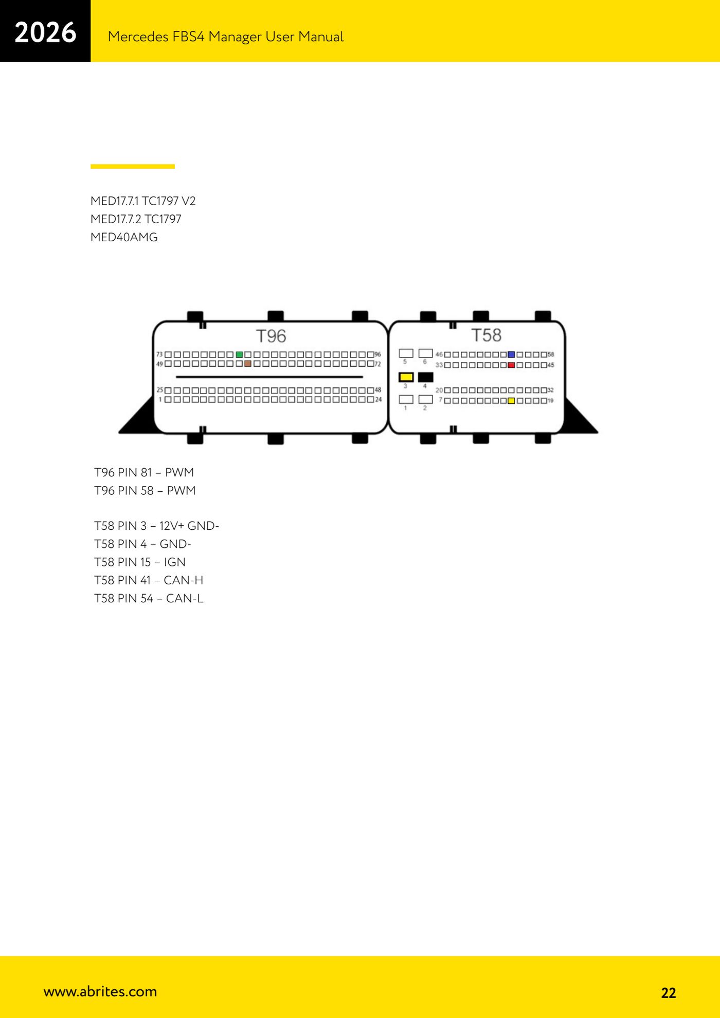
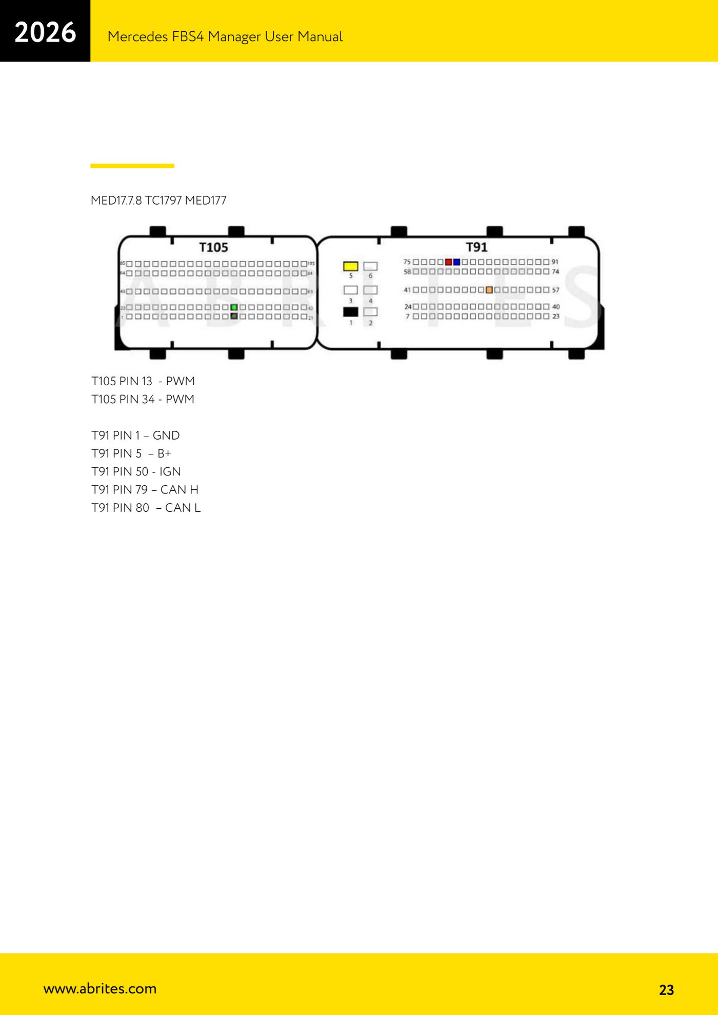
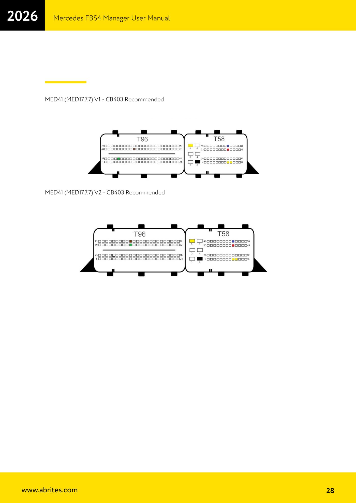
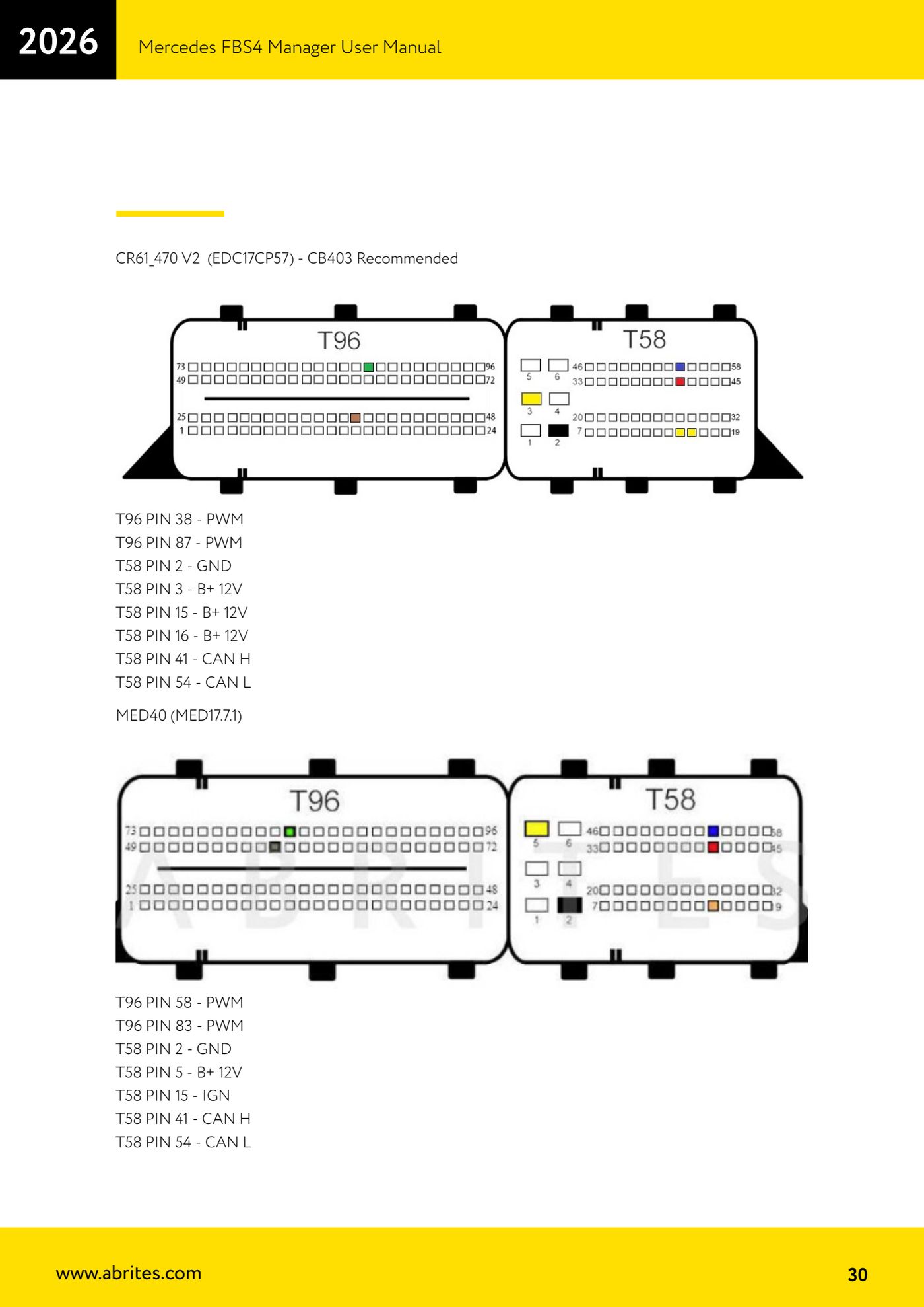
Pin-by-pin diagrams for bench-connecting the Bosch MED petrol ECUs in the Mercedes FBS4 range, needed for data reading, virginizing and personalization when OBDII is not enough. The wire colors are those of the CB401 cable.

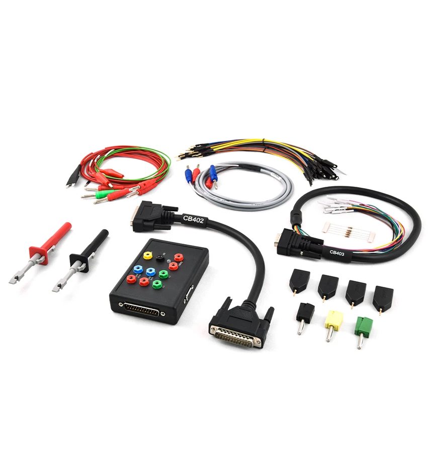
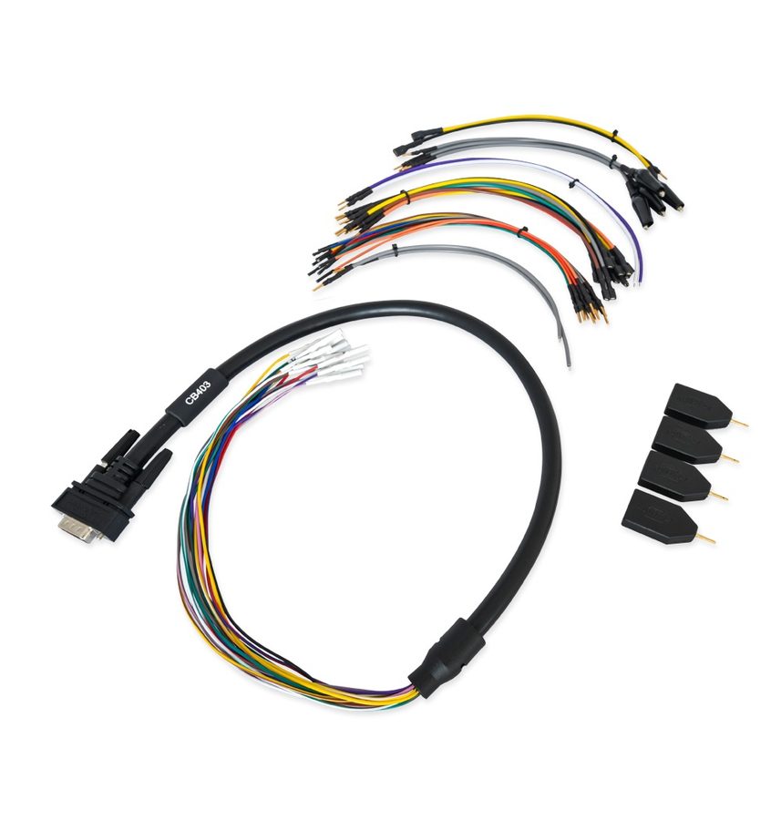
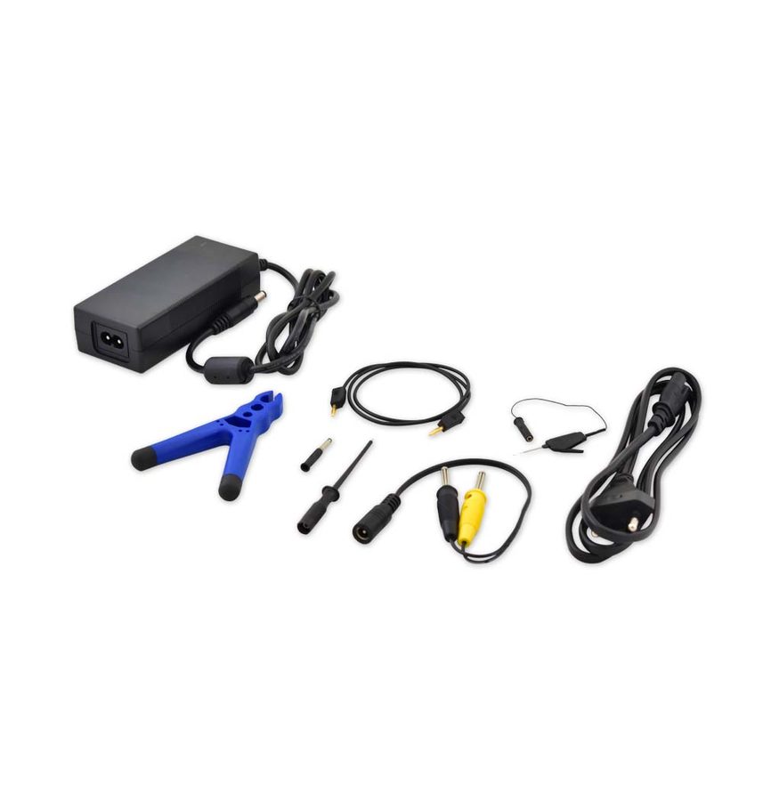
⚠ WarningOn MED41 (MED17.7.7) V1 and V2 the manual recommends using the CB403 cable. Always make sure the set-up is powered correctly (ZN074 recommended for the ZN051 DS Box) and that you follow exactly the pins given for the variant in front of you.
Procedure
- MED40 BOSCH, MED17.7.1 TC1797 V1, MED17.7.3 TC1797, MED17.7.3.1 TC1797 MED177, MED17.7.5 TC1793 MED177, MED177AMG, MED177V6LA: T96 PIN 83 - PWM; T96 PIN 58 - PWM; T58 PIN 2 - GND-; T58 PIN 5 - 12V+; T58 PIN 15 - IGN; T58 PIN 41 - CAN-H; T58 PIN 54 - CAN-L.
- MED17.7.1 TC1797 V2, MED17.7.2 TC1797, MED40AMG: T96 PIN 81 - PWM; T96 PIN 58 - PWM; T58 PIN 3 - 12V+; T58 PIN 4 - GND-; T58 PIN 15 - IGN; T58 PIN 41 - CAN-H; T58 PIN 54 - CAN-L.
- MED17.7.8 TC1797 MED177: T105 PIN 13 - PWM; T105 PIN 34 - PWM; T91 PIN 1 - GND; T91 PIN 5 - B+; T91 PIN 50 - IGN; T91 PIN 79 - CAN H; T91 PIN 80 - CAN L.
- MED40 (MED17.7.1): T96 PIN 58 - PWM; T96 PIN 83 - PWM; T58 PIN 2 - GND; T58 PIN 5 - B+ 12V; T58 PIN 15 - IGN; T58 PIN 41 - CAN H; T58 PIN 54 - CAN L.
- MED40 (MED17.7.2) and MED17.7.1 V2: T96 PIN 81 - PWM; T96 PIN 58 - PWM; T58 PIN 2 - GND; T58 PIN 5 - B+ 12V; T58 PIN 15 - IGN; T58 PIN 41 - CAN H; T58 PIN 54 - CAN L.
- MED41 (MED17.7.7) V1 and V2: follow the dedicated diagrams in the manual using the recommended CB403 cable; on the bench the MED41 (MED17.7.7) can also be worked with DS Box + CB401 and, in specific cases, with the CB403.
- Connect the AVDI to the ZN051 DS Box (CB402 cable), wire everything up according to the ECU diagram, power up the bench and only then open the FBS4 Manager, select ECU and press "Info" to check communication.
Reference screenshots
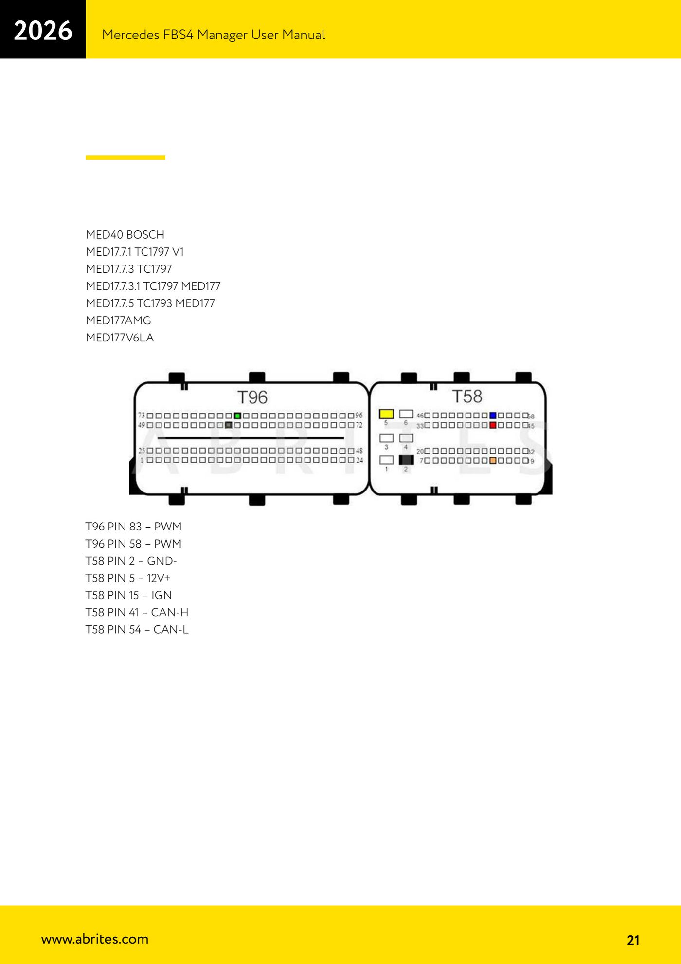
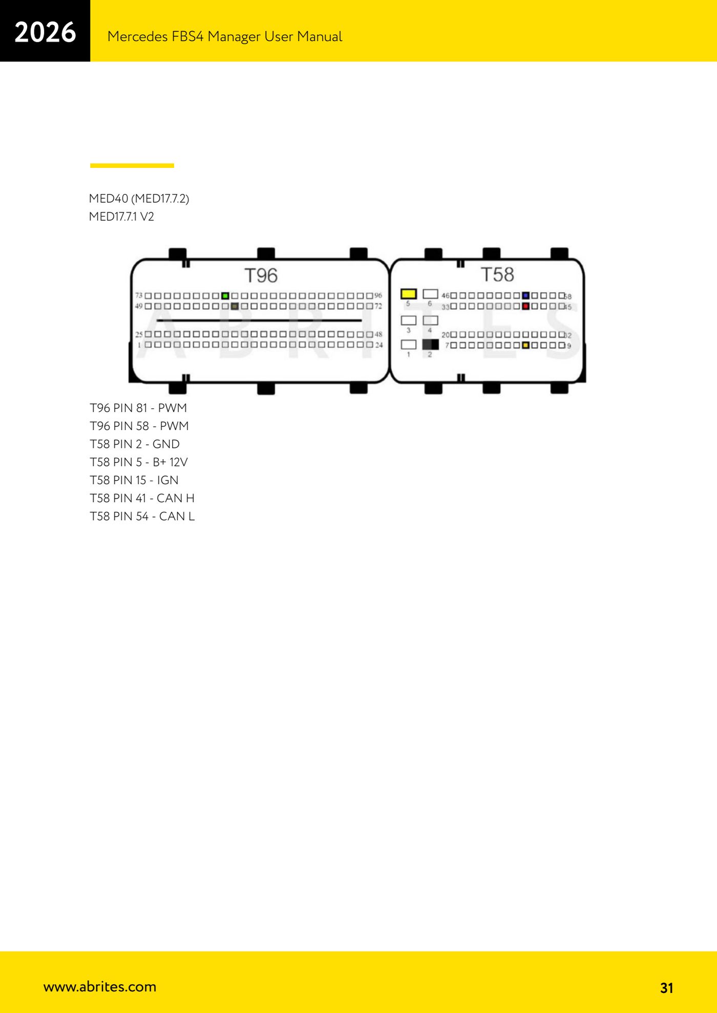
Source: Manuale Mercedes FBS4 Manager, parte 1 di 2, cap. 4.6 - ECU Bench Diagrams (p.21-23, 28, 30-31) · ⏱ estimated time 30-60 min
← All Abrites guides Hardware catalogue
More guides Mercedes
- Diagnostics and vehicle selection (VIN, chassis, over 1300 modules)
- Mercedes-Benz bus and truck diagnostics
- Mercedes Coding (VMAX, side sensors, parameters)
- Mercedes ECU Flashing (CFF files)
- Mercedes FBS4 Manager (722.9 and CRD3 renew, VIN change)
- Smart Functions (DPF mileage reset, DPF ash, VIM, seat belt alarm, sun roof, 360° cameras)
- FBS4 odometer correction with MN030 + emulators (EM008/EM014/EM018)
- Exhaust flaps — exhaust valve control
- CPC Torque limiter — torque limit
- VMax calibration — speed limiter
- Speed Limit Calibration — eVito 447 (electric)
- Mercedes AdBlue Reset: resetting the AdBlue system after component replacement or the remaining mileage warning